...
...
Geometry
| Include Page |
|---|
| Wind Turbine Blade - Panel |
|---|
| Wind Turbine Blade - Panel |
|---|
|
Geometry
| Note |
|---|
This tutorial is not being updated any more. We recommend that you follow this newer tutorial on fluid-structure analysis of a wind turbine blade. Thank you!
|
| Note |
|---|
For users of ANSYS 15.0, please check this link for procedures for turning on the Auto Constraint feature before creating sketches in DesignModeler. |
Downloading and Importing Geometry
Right click here and select Save link as... to download the geometry file. Save the file somewhere convenient, like your desktop or a working folder. In Workbench in the Project Schematic window, go to File > Import. In the Import window that opens, change the file type (next to the File Name text box) to Geometry File. Select the downloaded geometry file and press Open. The geometry should now be in the project schematic, as shown below. page, right click on Geometry and import the downloaded file.
 Image Added
Visualizing the Geometry
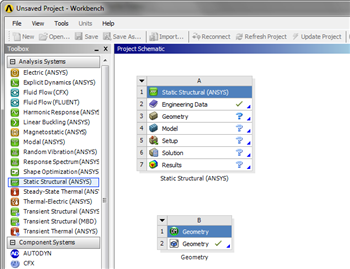 Image Removed
Next, we will open the file to generate the geometry. Double click the imported geometry  to open the Design Modeler. When the Design Modeler opens, a pop up window will ask us for the default units of measurement for the geometry. Select Meter and then press OK . After you select the units, you will notice the Graphics window is empty: this is because we need to generate the geometry by clicking
  Image Removed Once you press Image Removed, the imported geometry should show in the Graphics window.
 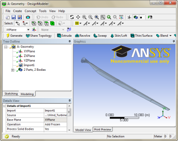 Image Removed
Next, we need to connect the geometry to our current project. Close the Design Modeler and return to the project schematic. First click (and hold) on the imported geometry box Image Removed Drag and drop on  Image Removed. When you are finished, a line should connect the two boxes showing that you have successfully linked them.
The wind blade geometry will be displayed in the graphics window in Design Modeler. The blue lines highlight the shape of the wind blade and the spar and the red line highlights five sections of the blade/spar. No further work is needed.
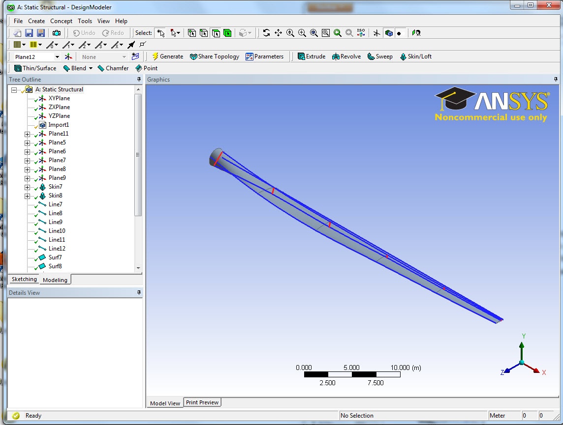 Image Added
| Info |
|---|
|
The original blade contained many geometric error when it was created in Solidworks. One major error was the connection between the wind blade and the spar. Thanks to Sean Harvey from ANSYS Inc., who has spent a great amount of work fixing the geometric errors on this wind blade. |
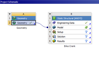 Image Removed
Now that the geometry is imported and generated, we are ready to mesh the geometry.
Go to Step 3 - : Mesh
Go to all ANSYS Learning Modules
 Sign-up for free online course on ANSYS simulations!