 Sign-up for free online course on ANSYS simulations!
| Panel |
|---|
Author: Matthew Blair Introduction |
| Note |
|---|
Under Construction! |
| Info | ||
|---|---|---|
| ||
If desired, you can complete the project without cRIO hardware present by using "offline configuration mode" for the hardware, which will simulate the presence of attached hardware. To use offline configuration and skip hardware setup, go to 3. Software Configuration. |
Hardware Setup
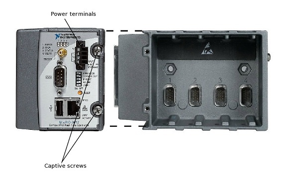
1. With no power connected, install the chassis onto the controller module, making sure to tighten the captive screws in the top face of the controller.
2. Install the I/O modules into the chassis in whatever location is most convenient.
3. Connect I/O modules to signal sources, if applicable. This will depend on the goal of your system and may not be possible if you choose to develop in a separate location from your application.
4. Connect a power source to the controller module, positive lead in the terminal labeled "V1" or "V2", negative lead in the adjacent terminal labeled "C". Refer to the documentation for your controller. Our example cRIO-9012 used lithium polymer batteries at ~16V. The 9012 also has the ability to automatically switch between power input from two power sources applied to the four power terminals, with the negative terminals as a common ground. Make sure your power source can be easily disconnected, as there is no “off” switch on the controller.
5. Connect the controller module to your Windows PC through an Ethernet cable. They need not be connected directly, so long as they are on the same Ethernet network.