| Include Page |
|---|
| ANSYS Google Analytics |
|---|
| ANSYS Google Analytics |
|---|
|
| Include Page |
|---|
| Cantilever Beam Modal Analysis - Panel |
|---|
| Cantilever Beam Modal Analysis - Panel |
|---|
|
...
Mesh
Launch Mechanical
(double click) Model,  , in the "Cantilever Modal" project.
Generate Default Mesh
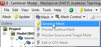
First, (click on ) Mesh in the tree outline. Next, 0 (click) Mesh > Generate Mesh as shown below.
Size Mesh
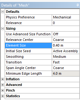
In this section we will size the mesh, such that it has ten uniform elements. In order to size the mesh, first expand Sizing located within the
Details of "Mesh" table. Next, set Element Size to 0.40 m, as shown below.
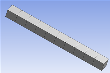
Now, (click) Mesh > Generate Mesh in order to generate the new mesh. You should obtain the mesh, that is shown in the following image.
| newwindow |
|---|
| Click Here for Higher Resolution |
|---|
| Click Here for Higher Resolution |
|---|
|
https://confluence.cornell.edu/download/attachments/145756994/10ElemMesh_Full.png |
Note that in this simulation we are working with beam elements, which are simply line segments. As a visualization tool ANSYS displays a beam with width and height. In order to display the actual mesh (click) View > (deselect) Thick Shells and Beams. You will then see the mesh displayed in its native form.  Image Added
| newwindow |
|---|
| Click Here for Higher Resolution |
|---|
| Click Here for Higher Resolution |
|---|
|
https://confluence.cornell.edu/download/attachments/145756994/LineMesh_Full.png |
Save
Go to Step 4: Setup (Physics)
See and rate the complete Learning ModulePhysics Setup
Go to all ANSYS Learning Modules
 Sign-up for free online course on ANSYS simulations!