 Sign-up for free online course on ANSYS simulations!
...
Now will assign names to some of the edges to make creating boundary conditions for the mesh easier. Let's recall the boundary conditions we planned in the Pre-Analysis Step:
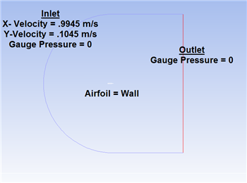
The edges highlighted blue are the inlet, the edges highlighted red are the outlet, and the airfoil is highlighted white in the middle. Now we are ready to name the sections. In the Outline window, select geometry - this will make selecting seeing the edges a little easier. Again make sure the edge selection tool  is selected. Now, select the two vertical edges on the far right side of the mesh. Right click, and select Create Named Selections. Name the edges
 outlet.  . Next, select the edges that correspond to the inlet of the flow as defined by the picture above. Again, right click and select Create Named Selections and this time name the selection
 inlet. Finally, select the two edges making up the airfoil, and name the selection airfoil.
Go to Step 4 - Setup (Physics)
Go to all FLUENT Learning Modules