 Sign-up for free online course on ANSYS simulations!
...
Although we are only looking for the strain at the strain gauge location, we should also check the deformation of the crank to see if it makes intuitive sense. This will allow us to catch any errors we have made setting up the simulation. To add deformation to the solution, first click Solution  to add the solution sub menu to menu bar
...
In the Solution sub menu select Strain > Normal. Now, we need to specify that we want the strain to be measured at the stain gauge in the y direction. To accomplish this, go to Scoping Method > Path, the select Path > Strain Gauge in the details window. To change the direction of the strain, select Orientation > Y Axis. The rest of the default options should suffice for our simulation.
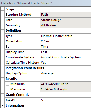
When all of the settings are finished, press Solve.
...