 Sign-up for free online course on ANSYS simulations!
...
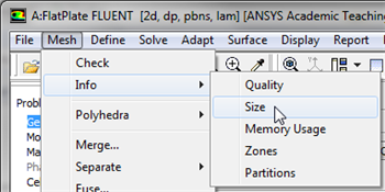
First, the mesh will be checked to verify that it has been properly imported from Workbench. In order to obtain the statistics about the mesh (Click) Mesh > Info > Size, as shown in the image below.
Then, you should obtain the following output in the Command pane.
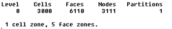
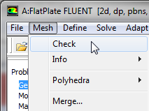
The mesh that was created earlier has 3,000 elements(50 x 60). Note that in FLUENT elements are called cells. The output states that there are 3,000 cells, which is a good sign. Next, FLUENT will be asked to check the mesh for errors. In order to carry out the mesh checking procedure (Click) Mesh > Check as shown in the image below.
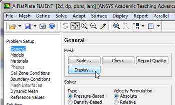
You should see no errors in the Command Pane pane. Now, that the mesh has been verified, the mesh display options will be discussed. In order to bring up the display options (Click) General > Mesh > Display as shown in the image below.
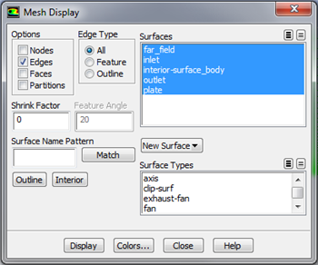
The previous step should cause the Mesh Display window to open, as shown below. Note that the Named Selections created in the meshing steps now appear.
| newwindow | ||||
|---|---|---|---|---|
| ||||
https://confluence.cornell.edu/download/attachments/118771050/MeshDispMenu_Full.png |
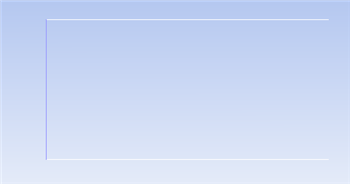
You should have all the surfaces shown in the above snapshot. Clicking on a surface name in the Mesh Display menu will toggle between select and unselect. Clicking Display will show all the currently selected surface entities in the graphics pane. Unselect all surfaces and then select each one in turn to see which part of the domain or boundary the particular surface entity corresponds to (you will need to zoom in/out and translate the model as you do this). For instance, if you select far_field, inlet, and plate and then click Display you should then obtain the following output in the graphics window.
Now, make sure all 5 items under Surfaces are selected. The
 button next to Surfaces selects all of the boundaries while the
  button deselects all of the boundaries at once. Once, all the 5 boundaries have been selected click Display, then close the Mesh Display window. The rectangle displayed in the graphics window corresponds to our solution domain. Some of the operations available in the graphics window to interrogate the geometry and mesh are:
 Translation: The model can be translated in any direction by holding down the Left Mouse Button and then moving the mouse in the desired direction.
Zoom In: Hold down the Middle Mouse Button and drag a box from the Upper Left Hand Corner to the Lower Right Hand Corner over the area you want to zoom in on.
Zoom Out: Hold down the Middle Mouse Button and drag a box anywhere from the Lower Right Hand Corner to the Upper Left Hand Corner.
Use these operations to zoom in and interrogate the mesh.
...
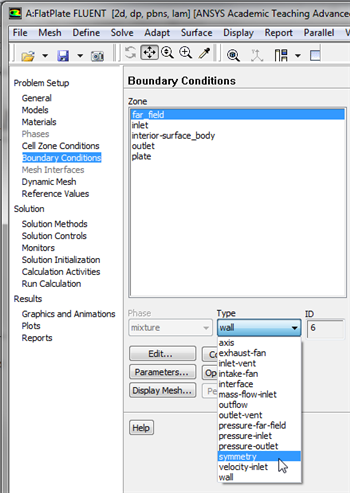
For the far_field, set the Boundary Condition Type to symmetry, as shown below.
| newwindow | ||||
|---|---|---|---|---|
| ||||
https://confluence.cornell.edu/download/attachments/118771050/symmbc_Full.png |
In the first dialog box click yes and in the second dialog box leave the name as is and click OK. The symmetry boundary conditions sets the velocities normal to the boundary equal to zero.
...