Sign-up for free online course on ANSYS simulations!
| Include Page | ||||
|---|---|---|---|---|
|
| Include Page | ||||
|---|---|---|---|---|
|
Geometry
For this problem, we are going to import the geometry into ANSYS from a CAD package. Download the part file here. Save the file somewhere convenient, like your desktop or your working directory.
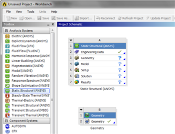
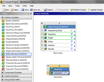
To open the file in ANSYS, go to File > Import. Browse to the geometry location on your computer. If you do not see the file, make sure you are browsing for geometry files (the pull down menu at the bottom right of the browsing window for computers running Windows 7). Select the Geometry and click Open. This will import your geometry into ANSYS. Your project window should now include the main project, and the newly imported geometry (see below).
| Info | ||
|---|---|---|
| ||
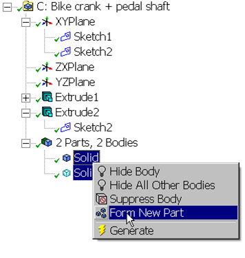
If you are importing 2 parts at once, i.e. a crank and a pedal shaft, you need to connect the two geometries in ANSYS. To accomplish this, look to the Outline window. There should be a box labeled 2 Parts, 2 Bodies. Expand the section, and there should be 2 solid parts underneath. To connect them, highlight both selections by holding down Ctrl and left clicking them. Right click, and select Form New Part. This will connect the two geometries and will allow you to carry on the simulation.
|
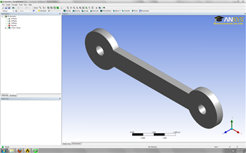
Now that the geometry has been imported, let's open the file and make sure everything is in order! Double click  . This will open the design modeler. When you are prompted, select Inch as your standard unit of measurement. The first thing you should notice is that the geometry is not there, so click
  to generate the geometry (be patient - it may take a couple of minutes). When the geometry finally generates, you should see the screen below.
Now that we have verified we are using the geometry we want, we need to tell ANSYS that this is the geometry we want to use. Close the Design Modeler and return to the project window. To connect the geometry to the project, click and drag the . As soon as you drag the box, ANSYS will highlight the geometry and model boxes in the main project.
Drag and drop the geometry box onto 
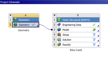
The geometry has been connected the project and we are ready for the next step.
Continue to Step 3: Mesh
Go to all ANSYS Learning Modules
See and rate the complete Learning Module
| Panel |
|---|
Author: Benjamin Mullen, Cornell University Problem Specification |
Geometry
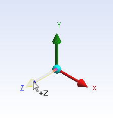
To open the design modeler, right click on Geometry on the project outline and click  . It will prompt you to pick the standard units. From the Problem Specification, we want to choose inch. To begin sketching, we need to look at a plane to sketch on. Click on the Z-axis of the compass in the bottom right hand corner of the screen to look at the x-y plane.