 Sign-up for free online course on ANSYS simulations!
...
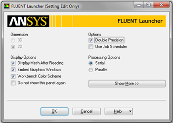
Double click on Setup in the Workbench Project Page which will bring up the FLUENT Launcher. When the FLUENT Launcher appears change the options to "Double Precision", and then click OK as shown below.The Double Precision option is used to select the double-precision solver. In the double-precision solver, each floating point number is represented using 64 bits in contrast to the single-precision solver which uses 32 bits. The extra bits increase not only the precision, but also the range of magnitudes that can be represented. The downside of using double precision is that it requires more memory.
| newwindow | ||||
|---|---|---|---|---|
| ||||
https://confluence.cornell.edu/download/attachments/118475240/DoublePrecision_Full.png |
Twiddle your thumbs a bit while the FLUENT interface starts up. This is where we'll specify the governing equations and boundary conditions for our boundary-value problem. On the left-hand side of the FLUENT interface, we see various items listed under Problem Setup. We will work from top to bottom of the Problem Setup items to setup the physics of our boundary-value problem. On the right hand side, we have the Graphics pane and, below that, the Command pane.
!TwoChecks_Full.png!
Check and Display Mesh
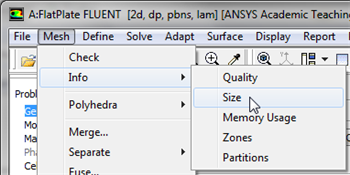
First, the mesh will be checked to verify that it has been properly imported from Workbench. In order to obtain the statistics about the mesh (Click) Mesh > Info > Size, as shown in the image below.
Then, you should obtain the following output in the Command pane.
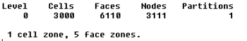
The mesh that was created earlier has 500 elements(5 Radial x 100 Axial). Note that in FLUENT elements are called cells. The output states that there are 500 cells, which is a good sign. Next, FLUENT will be asked to check the mesh for errors. In order to carry out the mesh checking procedure (Click) Mesh > Check as shown in the image below.
You should see no errors in the Command Pane. Now, that the mesh has been verified, the mesh display options will be discussed. In order to bring up the display options (Click) General > Mesh > Display as shown in the image below.
The previous step should cause the Mesh Display window to open, as shown below. Note that the Named Selections created in the meshing steps now appear.
| newwindow | ||||
|---|---|---|---|---|
| ||||
https://confluence.cornell.edu/download/attachments/118475240/MeshDisplayWindow_Full.png |
You should have all the surfaces shown in the above snapshot. Clicking on a surface name in the Mesh Display menu will toggle between select and unselect. Clicking Display will show all the currently selected surface entities in the graphics pane. Unselect all surfaces and then select each one in turn to see which part of the domain or boundary the particular surface entity corresponds to (you will need to zoom in/out and translate the model as you do this). For instance, if you select wall, outlet, and centerline and then click Display you should then obtain the following output in the graphics window.
Now, make sure all 5 items under Surfaces are selected. The
 button deselects all of the boundaries at once. Once, all the 5 boundaries have been selected click Display, then close the Mesh Display window. The long, skinny rectangle displayed in the graphics window corresponds to our solution domain. Some of the operations available in the graphics window to interrogate the geometry and mesh are:
 Translation: The model can be translated in any direction by holding down the Left Mouse Button and then moving the mouse in the desired direction.
Zoom In: Hold down the Middle Mouse Button and drag a box from the Upper Left Hand Corner to the Lower Right Hand Corner over the area you want to zoom in on.
Zoom Out: Hold down the Middle Mouse Button and drag a box anywhere from the Lower Right Hand Corner to the Upper Left Hand Corner.
Use these operations to zoom in and interrogate the mesh.
\h2. Step 4: Setup (Physics)
If you have skipped the previous mesh generation steps 1-3, you can download the mesh by right-clicking on this link. Save the file as plateBL.msh. Launch FLUENT.
Start > Programs > ANSYS 12.1 > Fluid Dynamics > FLUENT
Select Double Precision under Options and click OK.
...