 Sign-up for free online course on ANSYS simulations!
...
To set up the input and output parameters for a geometry created in Workbench, simply follow the steps below. To set up parameters for a geometry created in SolidworksSolidWorks, follow the instructions here.
Design Variables: Hole Radius
...
(SpaceClaim)
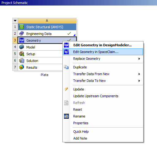
Parameters can be defined in SpaceClaim, even if the geometry was created in DesignModeler or another CAD software, as is the case for us. To do this, right-click on  from the Project Schematic window and choose "Edit Geometry in SpaceClaim..." as shown below:
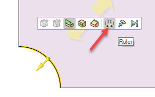
Once SpaceClaim has opened, go into the Design tab and choose the Pull tool. Select the arc that represents our hole and then choose the Ruler option from the mini toolbar that appears:
Now move the cursor until it snaps to the center of the arc:
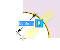
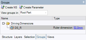
Now, click the box with the "P" to the right of the dimension. You can also go into the Groups tab and choose "Create Parameter" near the top of that window. This will create a parameter named Group1 under a folder called Driving Dimensions. Call the parameter "DS_R". You can always go back and rename your parameters by right-clicking on them and choosing "Rename" in the context menu that appears. If you click on your parameter, you can see the current dimension being used in the model. Make sure your Groups tab looks like the image below before continuing:
SpaceClaim can now be closed.
Design Variables: Hole Radius (DesignModeler)
This section applies only if you do not have access to SpaceClaim. In that case, you can also use DesignModeler (the older geometry engine) to specify your parametersThe radius of the hole needs to be declared a design variable. In order to do so first, open the Design Modeler DesignModeler by double-clicking on  from on from the Project Schematic window. Then expand XYPlane. Next, highlight Sketch1.
...
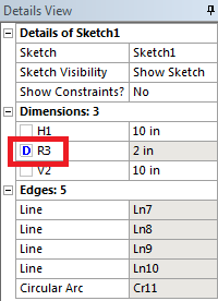
Now, check the box to the left of "R3", which will be in the "Dimensions: 3" part of the "Details View" table. When you check the box an uppercase "D" will appear within the box and you will be asked what to call the parameter. Call the parameter "DS_R".
The Design Modeler DesignModeler can now be closed.
Objective Function: Minimize Volume (& Mass)
...
Constraints: Maximum Von Mises Stress < < 32.5 ksiksi
Now, the maximum Von Mises Stress will be specified as an output parameter. In order to do so, (Expand) Solution > (Highlight) Equivalent Stress. In the "Details of "Equivalent Stress"" window, underneath Results, check the box to the left of Maximum. Once again a "P" should appear to the left of the box to illustrate to the user that the maximum Von Mises stress has been designated as an output parameter.
...
After doing so, we can see that DS_R is the input parameter, and the volume and max. value of the von Mises Stress are the output parameters. Now, return to the main window by clicking on the Project tab, or in older versions by selecting Return to Project.

Note: Make sure your parameters are using the correct units! If they are not, you will need to go back into Mechanical and change the units before unchecking and rechecking the box next to the parameters of interest. This should reset the units on the parameters in the Parameter Set window, but beware that this may cause the entire optimization process to need updated and repeated.
Go to Step 4: Design of Experiments
...