 Sign-up for free online course on ANSYS simulations!
...
Now that we have a good idea about the stress distribution, we will look specifically at solving the problem in the problem specification. First, we will look at the stress in the r-direction at r = 11.5 inches. In the outline window, click Solution > Sigma-r at r =11.5. This will bring up the stress in the r-direction along the path at r = 11.5 inches (from the center of curvature of the bar).
XXXXXXXXXXXXXPICTUREXXXXXXXXXXXXXXXXXXXXXX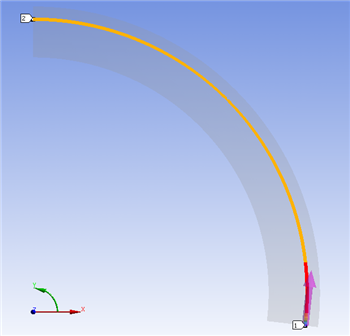
In the window below, there is a table of the stress values along the path. To find the value of sigma-r at r = 11.5 in, we again want to look far away from the transient stresses due to the moment. The path is defined in a counter-clockwise direction, so looking at the last value of the table should tell us the stress at r = 11.5 inches at the midpoint of the bar. This value of sigma-r is -57.042 psi.
Now, we will do the same for the stress in theta direction to determine sigma-theta at r = 11.5 inches. In the outline window, click Solution > Sigma-theta at r =11.5. This will bring up the stress in the theta-direction along the path at r 11.5 inches.
XXXXXXXXXXXXXXPICTUREXXXXXXXXXXXXXXXXXXXXX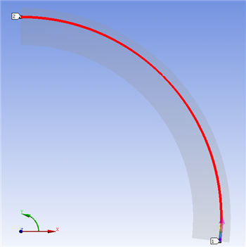
Look again at the table containing the stresses along the path. Look to the bottom of the table to find the stress in the theta-direction at the midpoint of the bar. We find that sigma-theta at this point is 910.950 psi.
Finally, we will examine the shear stress at r = 11.5 in. In the outline window, click Solution > Tau-r-theta at r =11.5.
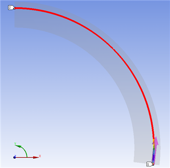
Again, look at the bottom of the table. You will find that the shear stress is very small at this point as we mentioned above.
...