 Sign-up for free online course on ANSYS simulations!
...
Before we dive in to the solution, let's take a look at the mesh used for the simulation. In the outline window, click Mesh to bring up the meshed geometry in the geometry window.
XXXXXXXXXXXXXXXXPICTUREXXXXXXXXXXXXXXXXXXXX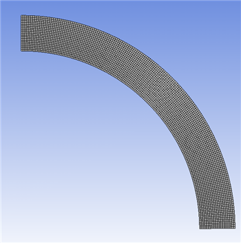
Look to the outline window under "Mesh". Notice that there are two types of meshing types on the geometry: a mapped face meshing and a face sizing meshing. The mapped face meshing restricts the type of element shapes that will be used in the mesh - in this case, quadrilaterals. The face sizing controls the size of the elements. The size of each element is limited to at most 0.1 square inches. Another thing to notice about the geometry is that the geometry in the simulation is actually only one half of the geometry from the problem statement. This is done using symmetry constraints which allows the simulation can find the same answer as for the full geometry while saving valuable computation time because it is using fewer elements!
...