 Sign-up for free online course on ANSYS simulations!
| Include Page | ||||
|---|---|---|---|---|
|
...
| Include Page | ||||
|---|---|---|---|---|
|
Physics Setup
Specify Material
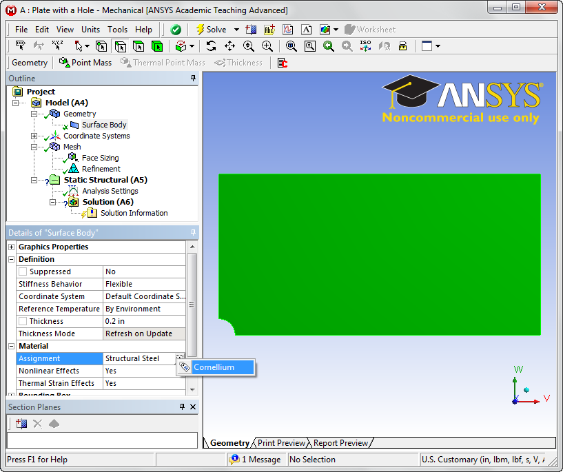
First, we will tell ANSYS which material we are using for the simulation. Expand Geometry, and click Surface Body in the Outline window. In the Details window, select Material > Assignment > Cornellium. The material has now been specified.
| newwindow | ||||
|---|---|---|---|---|
| ||||
https://confluence.cornell.edu/download/attachments/128616960/MatAssign.png?version=1&modificationDate=1320619527000 |
Symmetry Conditions
First, let's start by declaring the symmetry conditions in the problem. Right click Model > Insert > Symmetry.

| newwindow | ||||
|---|---|---|---|---|
| ||||
https://confluence.cornell.edu/download/attachments/128616960/ModSym.png?version=1&modificationDate=1320619676000 |
This will create a symmetry folder in the outline tree .  Now, right click Symmetry > Insert > Symmetry Region. Make sure the Edge Select Tool is highlighted and select the left edge above the hole.
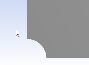
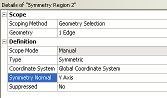
Now look to the Details View window and select Geometry > Apply. This should create a red line with a tag on the model. Ensure that under Symmetry Normal the x-axis is selected. Repeat this process to create a symmetry region for the bottom edge to the right of the hole, but this time making sure that the Symmetry Normal parameter is the y-axis.
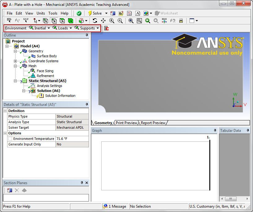
Forces
Now, we can specify the forces on the body. Click Static Structural in the outline tree. This will bring up the Physics Sub-Menu bar in the Environment. Clock Loads > Force to specify a forceMenu Bar.
| newwindow | ||||
|---|---|---|---|---|
| ||||
https://confluence.cornell.edu/download/attachments/128616960/LoadEnvironment.png?version=1&modificationDate=1320620076000 |
Click Loads > Pressure to specify a traction. Select the right edge of the geometry and apply it in the details view window. Now we want to define the force as components, so select Define By > Components. Specify the x-component magnitude to 50,000 lbs (Remember! We are only using 1/4 of the geometry and 1/2 of the original cross sectional area. Therefore, we can only use half of the force!). The pressure's magnitude from the problem specification is -1e6 psi (pressure in ANSYS defaults to compression, and we need tension, hence the negative sign). Now that the forces have been set, we need to set up the solution before we solve.