 Sign-up for free online course on ANSYS simulations!
| Include Page |
|---|
...
|
...
|
| Include Page | ||
|---|---|---|
|
Geometry
...
|
Geometry
| Note |
|---|
For users of ANSYS 15.0, please check this link for procedures for turning on the Auto Constraint feature before creating sketches in DesignModeler. |
Analysis Type
First, right click Geometry  and click Properties to bring up the geometry properties menu. The default analysis type of ANSYS is 3D, but we are doing a 2 dimensional problem. Change the Analysis TypesType from 3D to 2D . Now, right click on Geometry on the project outline and click

Next double click . This will bring up the Design Modeler. It will prompt you to pick the standard units. From the Problem SpecificationSince all of the units in the problem specification were given in English units, we want to choose inch . When the Inch radio button is selected, press OK
Draw the Geometry
To begin sketching, we need to look at a plane to sketch on. Click on the Z-axis of the compass in the bottom right hand corner of the screen to look at the x-y plane.
...
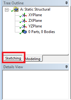
Now, look to the sketching toolboxes window and click the sketching tab; this will bring up the sketching menu.
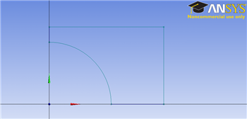
Before we sketch the geometry, let's not note something about the problem specification. The geometry itself has two planes of symmetry: it is symmetric about the x-plane and y-plane. This means we can model 1/4 of the geometry, and use symmetry constraints to represent the full geometry in ANSYS. If me model a quarter of the geometry, we can make the problem less complex and save some computational time.
...
We almost have a geometry, but we first need to get rid of the superfluous lines. In the sketching toolboxes window, click Modify > Trim .
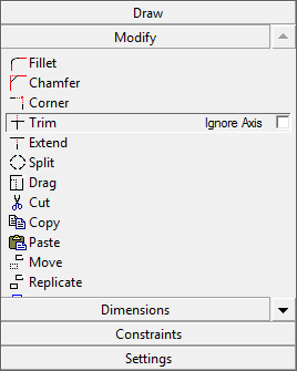
Now, trim the segments that are 1. outside of the 1st quadrant, and 2. between the cirle circle and the origin. You should end up with something similar to the following figure.
Dimensions
Now, we have to dimension the drawing to the problem specification. (Remember! We are only drawing 1/4 of the geometry, so we need to take this into account when dimensioning the figure in ANSYS). In the sketching toolboxes window, click Dimensionins Dimensions > General
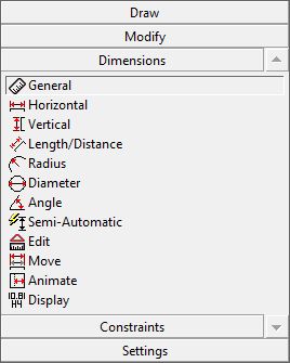
This tool will allow you to define dimensions that you can specify. We need to specify the rectangle's length and width, and the circle's radius. Use the tool to define the height of the rectangle (the right edge of the geometry), the length of the rectangle (the top edge of the rectangle), and the radius of the circle. You should end up with the following window.
...
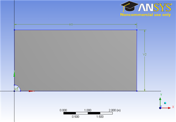
Change the H (for horizontal) dimension to 5 inches, the V (for vertical) dimension to 2.5 inches, and the R (for radius) dimension to .25 inches. Now we have the geometry specified in the problem statement sketched in ANSYS.

Create a Surface from the Sketch
Next, we need to tell ANSYS what type of geometry we are modeling. For this problem, we will create a surface and give it a thickness. In the menu bar, select Concept > Surfaces from Sketches . To select the sketch, look to the outline window, and select expand XY plane > Sketch 1 .

In the details window pane, select Base Objects > Apply . Now, we need to specify a thickness. Specify the thickness as .1 inches, as from the problem statement. Now in the menu toolbar, click  This should generate the geometry.
Close the Deign Modeler (don't worry, the geometry will be saved in the project automatically). Now we are ready to mesh the geometry.