 Sign-up for free online course on ANSYS simulations!
...
First, click on the sketching tab,  , which is located underneath the "Tree Outline". Next , click on the rectangle button,
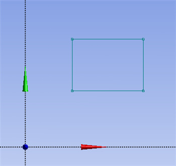
  , and draw a rectangle somewhere above the x axis in the top right quadrant of the XY Plane as shown below.
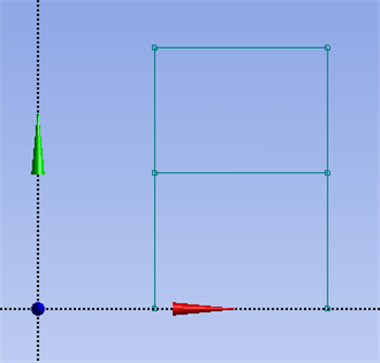
Next, click the line button,  , and draw two vertical lines that connect the bottom left and the bottom right corners of the rectangle to the x axis. Remember that a "P" should appear when the mouse is directly over a rectangle corner and a "V" should appear when the line your drawing is vertical. Lastly, make sure that a "C" appears before you click on the x axis to terminate the line segments. You should now have an image comparable to the one below.
Dimensioning
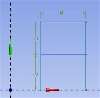
Now, the dimensions of the plane frame structure will be inputted into ANSYS. The plane frame structure has symmetry in its geometry, so "equal length" constraints will be used in order to shorten the dimensioning process. First, click on the "Constraints" tab,  , then click on the "Equal Length" button,
  . Now, click on the two vertical sides of the rectangle you drew, then click on the two vertical lines you drew. Next, click on the "Dimensions" tab,
  , and select "General",
  . Now, click on bottom left vertical line and click once more to place the marker. Repeat this action with the upper left vertical line and the top horizontal line. Your Design Modeler window should look similar to the image below.
See and rate the complete Learning Module
...