...
...
...
...
3. Mesh
Double Click on "Model", Image Removed , in order to start Mechanical .
Mesh
Use one element per member.
At this point the number of elements along each line segment will be specified. First right click on the "Mesh" tab,  Image Removed, then click "Insert" and finally click "Sizing" as shown below.
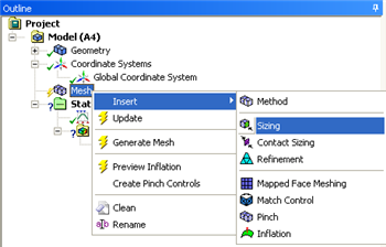 Image Removed
Next, click on the "Edge Selection" button,  Image Removed. Now hold down control and click on all six line segments. All the lines should now be highlighted in a light green color. Now, click the "Apply" button which will be located within the "Details of Edge Sizing" table. Now, change the "Type" to "Number of Divisions" as shown below.
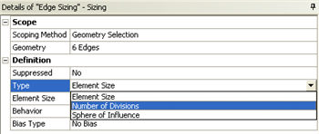 Image Removed
Set "Number of Divisions" to 1 and click update,  Image Removed, to generate the mesh. Expand "Mesh", Image Removed , and then click on "Edge Sizing",
  Image Removed. You should now see an image similar to the one below.
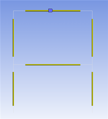 Image Removed
The single yellow bar on each line segment conveys that there is only one element per line segment.
Go to Step 4: Setup (Physics)See and rate the complete Learning ModulePhysics Setup
Go to all ANSYS Learning Modules
 Sign-up for free online course on ANSYS simulations!