 Sign-up for free online course on ANSYS simulations!
| Include Page | ||||
|---|---|---|---|---|
|
| Include Page | ||||
|---|---|---|---|---|
|
Geometry
| Note |
|---|
For users of ANSYS 15.0, please check this link for procedures for turning on the Auto Constraint feature before creating sketches in DesignModeler. |
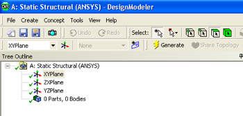
Double-click on the geometry button,  , in the Project Schematic area, which should launch the Design Modeler in ANSYS. Choose meter as the desired length unit. A folder called "A: Static Structural (ANSYS)" should be expanded in the tree outline of the Design Modeler. If it is not expanded, then expand it now.
Proper Orientation
...
Line Sketching
...
Assume that the cross-section is square. Then, to get the right values of EI and EA, you need to pick:
- Each side of the square is 0.346 m
- The Young's Modulus E is 2.08e10 Pa
Don't forget to assign the Young's modulus later in the Physics Setup.
Dimensioning
...
Line Body
...
Cross Section
...
3D Rendering
...
Transfer "Line Bodies" to Mesher
Note: This step needs to be done only in version 13.0. It can be skipped in version 14.0 and later.
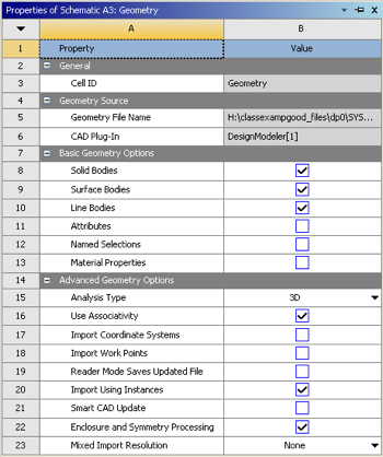
In order to make sure to get the geometry data transferred to the Model a couple of steps must be taken. First, right click on "Geometry" then click on "Properties". Under "Properties of Schematic A3: Geometry" expand "Basic Geometry Options" and check the box to the right of "Line Bodies" as seen below.
...