 Sign-up for free online course on ANSYS simulations!
| Include Page | ||||
|---|---|---|---|---|
|
| Include Page | ||||
|---|---|---|---|---|
|
Exercises
Exercise 1
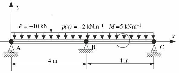
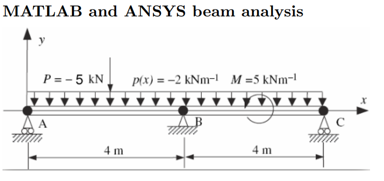
Consider a two-span beam shown above. The beam is subjected to uniformly distributed loading, point force at x=2m and moment at x=6m about the Z-axis, as shown. The beam bending stiffness is EI=2 x 10^7 Nm^2.
Using ANSYS, plot the deflection, bending moment, and shear force distribution of the beam. If you have four elements, what is the optimal mesh? Repeat the solution with an eight-element mesh. Comment on the results. Is your solution right? How can you improve the finite element solution?How many elements are necessary to get a good solution?
Tips:
- In ANSYS, you need to specify E and I separately. You can pick them independently as long as you get the desired EI. You specify I by specifying the cross-section as we saw in the preceding tutorial. To keep things simple, just pick a square cross-section as in the tutorial. Keep the cross-section dimensions small compared to the beam length to get a slender beam. ANSYS uses the Timoshenko beam formulation which is more general than the Euler-Bernoulli formulation. The difference between the two formulations becomes significant only when the beam is non-slender.You can pick E=2e11 (default) and calculate the equivalent square cross-section.
- Model the geometry using four lines. You will need to have vertices where you will be applying forces, moments or displacement constraints.
- Apply a distributed load using Line Pressure (see snapshot further down this page). In version 17, you can select all four lines when applying the line pressure. But in version 16 and prior versions, when you apply the line pressure, you can select only one line at a time. Since there are four lines in total, you'll need to apply line pressure four times.
- Apply the simply supported constraints using Supports > Displacement. For example, the settings in the figure below can be used to apply the simply supported constraint at A or C. Note that As we saw in the tutorial, ANSYS uses a generalized 3D beam formulation which includes z displacements. Since we don't have any deformation displacement in the z direction, you can set the z displacements in simply supported conditions displacement to zero.
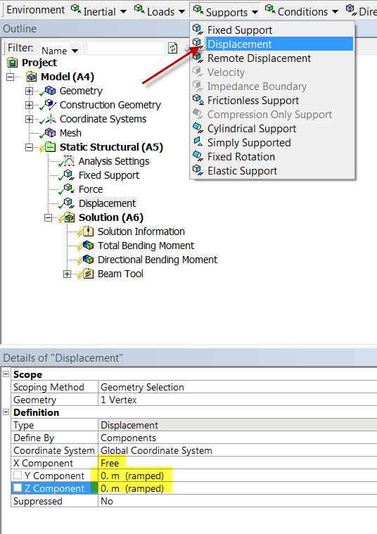 . You really need to do this at two vertices only. This will prevent the beam from translating in the z-direction and rotating about the y-axis. Otherwise, the problem becomes ill-posed, the stiffness matrix cannot be inverted and ANSYS will report a vague "solver pivot error".
 - You also need to add a constraint at one vertex to prevent rotation about the x axis as discussed in the truss tutorial in our free online ANSYS course at edx.org. This can be done by selecting Supports > Fixed Rotation as shown below.
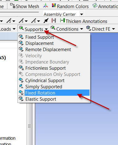 In the ANSYS model , you have to add an extra constraint by fixing the rotations about x and y axes at the right end (see snapshots below). Otherwise you might get a solver pivot error. This is because ANSYS is using a 3D beam element with these additional rotations as dof's. Adding the fixed rotation will zero out these additonal dof's.
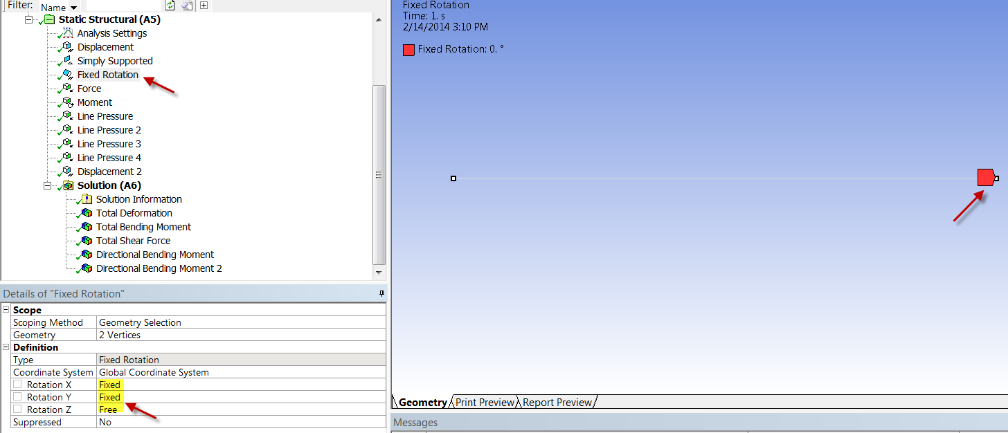
Exercise 2: Distributed Load
...
Problem Specification (pdf file)
| HTML |
|---|
<iframe width="560" height="315" src="https://www.youtube.com/embed/Nq1qLWIqICU" frameborder="0" allowfullscreen></iframe> |
Quick Video Summary:
- creating new coordinate systems
- positioning coordinating systems to create construction geometry
- determine displacements at any location
- how to create a mid-beam surface to determine the stresses along the midplane of the beam
...