 Sign-up for free online course on ANSYS simulations!
| Panel |
|---|
Problem Specification |
...
There are two options for creating the eight vertices: we can use the mouse after pressing the Click SD Points button, or we can enter the coordinates directly into the edit boxes under Vertex positions. We'll use the latter option. Enter the above coordinates in the corresponding edit boxes under Vertex positions as shown below. You can use MATLAB expressions within these boxes. For instance, for the x coordinate of the fifth vertex, enter cosd(30)-0.5*sind(30) under Xpos. Remember to use the correct trig function for how you express your angles: if you enter the angle in degrees, you must use the MATLAB functions sind and cosd, if you enter the angle in radians you must use the MATLAB functions sin and cos.
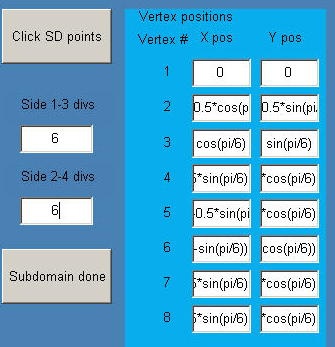
Next, we need to enter the number of divisions for each side. This specifies the number of elements that will be created along each side. Opposite sides need to have an equal number of divisions. So, in the above schematic of vertex positions, sides 1 and 3 should have an equal number of divisions as should sides 2 and 4. (Notice that sides are numbered in the same counterclockwise order as vertices, starting at the first vertex.) We'll use 6 divisions for each side. So enter 6 for Side 1-3 divs as well as Side 2-4 divs (see above figure).
Click on Save SD to create the subdomain. Since we have only one subdomain, select No in reponse to "Do you want to add another subdomain?". A dialog box pops up asking "Do you want to review the mesh coordinates"? This is the point at which you can review and correct any mistakes in creating the subdomain. Select Yes. Make sure the vertex positions have been entered correctly and click on Accept SD.
You will get a message saying that there are "0 internal boundaries". This is so because we have only one subdomain. In the Mesh Base Name window, enter rect as the Filename and click OK. Check that the file rect_mesh.dat has been saved in your working folder. The finite-element mesh is displayed in the MappingMeshTool GUI.
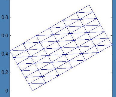
This completes mesh creation. Click on Mesh Complete. This puts us back in the main redAnTS GUI. We see under Current Settings that rect_mesh.dat is the mesh file we are working with. To plot the mesh in this GUI, click on the drop-down menu under Plotting and select Mesh.
Let's keep the fun going by moving on to Step 3 where we will specify inputs such as material properties and boundary conditions.Now that the geometry has been created in redAnTS, we now need to proceed to Step 3
Go to Step 3: Setup (Physics)Mesh
See and rate the complete Learning Module
...