 Sign-up for free online course on ANSYS simulations!
| Include Page |
|---|
...
|
...
|
| Include Page |
|---|
...
|
...
|
...
Step 6: Results
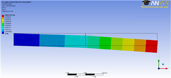
Total Deformation
First, examine the total deformation by clicking on the Total Deformation button,  . If you have used only two elements, you should see the output shown below.
...
https://confluence.cornell.edu/download/attachments/125812731/2ElemTotDef_Cornellian_Full.png...
https://confluence.cornell.edu/download/attachments/125812731/10ElemTotDefCornellian_full.png...
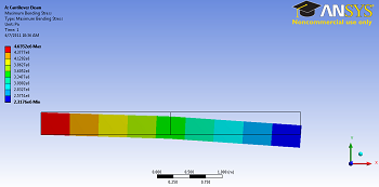
Maximum Bending Stress
For this static structural problem, the maximum bending stress is of interest. In order to examine the maximum bending stress first expand the Beam Tool folder,  , which is located under "Solution(A6)". Next, click on the Maximum Bending Stress button,
  . If you have used only two elements, you should obtain the following output.
...
https://confluence.cornell.edu/download/attachments/125812731/2elemmaxbendavg_full.png...
Plot Deformed Shape of Midline
| HTML |
|---|
<iframe width="560" height="315" src="https://www.youtube.com/embed/Zf9zYFNXkaI" frameborder="0" allowfullscreen></iframe> |
Plot Bending Stress
| HTML |
|---|
<iframe width="560" height="315" src="https://www.youtube.com/embed/_04tFkcaqXw" frameborder="0" allowfullscreen></iframe> |
Plot Bending Moment
| HTML |
|---|
<iframe width="560" height="315" src="https://www.youtube.com/embed/t2uTPPyIVEI" frameborder="0" allowfullscreen></iframe> |
Probe Displacement
| HTML |
|---|
<iframe width="560" height="315" src="https://www.youtube.com/embed/SA-rmkqkbm0" frameborder="0" allowfullscreen></iframe> |
Check Your Understanding
Select the correct option below.
Consider the case where we replace our square cross-section in ANSYS with an I-shaped cross-section that is taller, has a lower cross-sectional area and the same moment of inertia. If we then re-solve the problem in ANSYS, which of the following results would be affected? Select all options that apply.
Bending Moment
To view the bending moment along the beam, click Total Bending Moment in the Outline window. You should see the following in the graphics window.
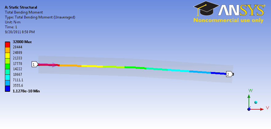
...
https://confluence.cornell.edu/download/attachments/125812731/BendingMoment.png?version=1&modificationDate=1316567309000Also notice that the values were plotted in a graph in the Graph window.
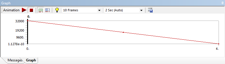
...
Deformed shape of the midline, u_y(x)
Max. bending stress at root
Go to Step 7: Verification & ValidationSee and rate the complete Learning Module