 Sign-up for free online course on ANSYS simulations!
!insertbeamtool.png!
| Include Page | ||||
|---|---|---|---|---|
|
Step 5: Solution
Solve For The Displacements
...
| Include Page | ||||
|---|---|---|---|---|
|
Numerical Solution
Obtain the Numerical Solution
| HTML |
|---|
<iframe width="560" height="315" src="https://www.youtube.com/embed/nkGwcByJqiY" frameborder="0" allowfullscreen></iframe> |
Check Your Understanding
Select the correct option below.
At this point, ANSYS has determined the degrees of freedom at the nodes. If we tweak any of these degrees of freedom, the corresponding deformed shape of the midline will change. How is the total potential energy of the beam affected in the process?
It:
- Decreases
- Stays the same
- Increases
Go to Step 6: Numerical Results
Post-Processing
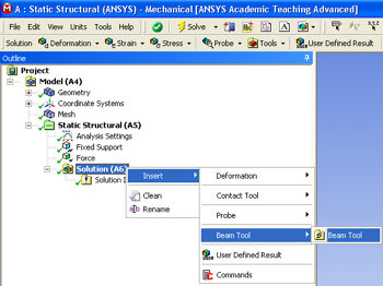
First, click on the solution button,  , in the workbench window. Next, right click on the "Solution (A6)" folder, then click insert, then click Beam Tool and finally click Beam Tool as shown in the image below.
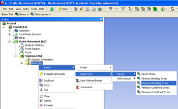
Next, right click on the "Beam Tool" folder that you have just added, then click on insert, then click on Beam Tool, then click on stress and finally click on Maximum Bending Stress as shown below.
In order to get ANSYS to execute the post-processing you must click the solve button,  , again.
Go to Step 6: ResultsSee and rate the complete Learning Module