...
...
...
...
...
Physics
...
Open the Model Window
...
Setup
...
Fix The Left Side of The Beam
...
Specify Young's Modulus
| HTML |
|---|
<iframe width="560" height="315" src="https://www.youtube.com/embed/SWRnNrWwrZU" frameborder="0" allowfullscreen></iframe> |
Specify Boundary Conditions
| HTML |
|---|
<iframe width="560" height="315" src="https://www.youtube.com/embed/TIMyW47UHW0" frameborder="0" allowfullscreen></iframe> |
Go to Step 5: Numerical Solution
Apply a Point Force to The Right Side of The Beam
Once again, click on the vertex pointer option,  Image Removed, but now click the right edge of the line body. A green box should now appear on the right side of the line body as seen below.
 Image Removed
Right click on the Static Structural folder again, then click insert and this time select Force as shown below.
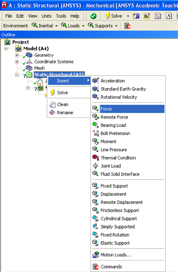 Image Removed
At this point, there should be a "Details of "Force"" window in the lower left corner of the Setup window. Expand "Definition" if it is not already expanded and then change "Define by" to Components as seen below.
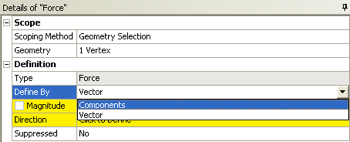 Image Removed
Now, click on the box to the right of Y Component without clicking the Y component button and change the force to -8000N. That is, you should NOT check the box to the left of Y Component. Your "Details of "Force"" window should now look very similar to the following image.
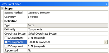 Image Removed
You should also see the following downward facing red arrow on the right side of the line body.
 Image Removed
The fixed end and the point force have now been applied.
Leave the Setup window open for the next step.
Go to Step 5: SolutionSee and rate the complete Learning Module
Go to all ANSYS Learning Modules
 Sign-up for free online course on ANSYS simulations!