Sign-up for free online course on ANSYS simulations!
Step 2: Geometry
Double-click on the geometry button,  , in the Project Schematic area, which should launch the Design Modeler in ANSYS.
A folder called "A: Static Structural (ANSYS) should be expanded in the tree outline of the Design Modeler. If it is not expanded, then expand it now.
...
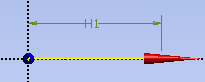
Next, click on the blue horizontal line that you drew. The blue horizontal line should have changed from blue to yellow as can be seen below.
In the "Details View" column a yellow box to the right of "Base Objects" should be highlighted in yellow. Click on the yellow box and then click apply. Then, click on the "Generate" button which has a lightening bolt on it and is located on the top left portion of the Design Modeler.
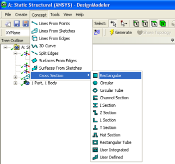
Now, a cross section will be given the line body. First go to "Concept" then go click on "Cross Section" then finally click on "Rectangular", as shown below.
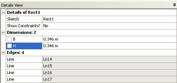
Now, the width and height of the cross section need to be defined. Under "Details View" set B to 0.346 meters and set H to 0.346 meters, as can be seen below.
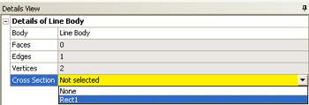
Then click on the Generate button,  . Now the defined cross section will be "merged" with the line body. First, expand "1 Part, 1 Body" which is located in the "Tree Outline". Next, click on "Line Body", and there should be a yellox box to the right of Cross Section under the "Details of Line Body". Click on the yellow box and select "rect1" as seen below.
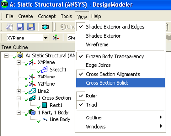
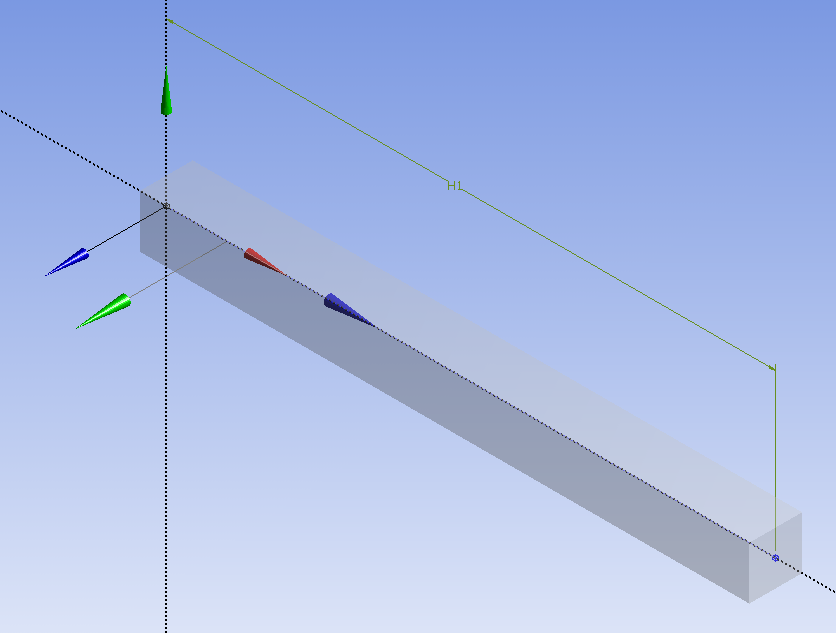
At this point the specified geometry can be checked in order to make sure all has gone well. Click on "View" and then "Cross Section Solids", as shown below.
If you click on the "1 Cross Section", 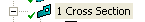 , in the Tree Outline and then click on the light blue dot,
  , you should now see a three dimensionally rendered beam in an isometric view.
At this point, the Design Modeler window can be closed.
Exporting The Geometry to The Model
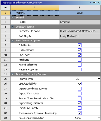
In order to make sure to get the geometry data transferred to the Model a couple of steps must be taken. First, right click on "Geometry" then click on "Properties". Under "Properties of Schematic A3: Geometry" expand "Basic Geometry Options" and check the box to the right of "Line Bodies" as seen below. Double-click on the geometry button in the Project Schematic area, which should launch the Design Modeler in ANSYS.