 Sign-up for free online course on ANSYS simulations!
...
Click once on the XYPlane button,  . Next, click once on the royal blue Z vector (displayed below) which should be in the bottom right section of the Design Modeler window.
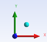
Now, you should be looking directly at the XY plane and the axises in the bottom right corner should be oriented as they are in the image below.
Click once on the "Sketching" Tab Sketching tab, 
, which appears at the bottom of the Tree Outline.
Click once on "Line" the Line button , 
, in the " Draw " tab, 
, that automatically appears. Then place the mouse cursor directly over the origin of the XY plane unit a P appears. Once the P appears then click once on the mouse. Next, move the mouse over to the right so it lies somewhere on the positive x axis. Prior, to clicking again make sure that a C appears. You should now have a line that starts a the origin and terminates somewhere on the positive axis.
At this point, the dimension of the line needs to be specified, so click once on the "Dimensions" tab. Then, click once on "Horizontal". The next step is to click somewhere on the y axis and then click on the endpoint of the line (the point that lies upon the positive x axis). Now, raise the cursor (which should now be a horizontal line and a pencil) above the line and click once. You should see a dimension labeled H2 above the horizontal line. Now, the length of the line will be manually edited. Underneath the "Sketching Toolboxes" there will be a column called "Details View". In "Details View there is a subcategory called "Dimensions: 1". Change the numerically value of H1 to 4 meters and press enter.
...