 Sign-up for free online course on ANSYS simulations!
| Include Page |
|---|
...
|
...
|
| Include Page |
|---|
...
|
...
|
Geometry
Initial settings
...
Proper Orientation
...
Line Sketching
First instinct is to make a rectangular solid as a model for our cantilever; While this would work, it would make the mesh more complex than it needs to be. This is a one-dimensional problem, so all we really need at our base is a one-dimensional figure: a line; (We still need to tell ANSYS it has volume, though.)
...
Line Body
...
The following videos use the legacy geometry engine, DesignModeler. Please see this page of the EdX course for updated instructions using the new geometry engine, SpaceClaim.
Sketch the Midline
| HTML |
|---|
<iframe width="560" height="315" src="https://www.youtube.com/embed/Lm9Z_3eMAQc" frameborder="0" allowfullscreen></iframe> |
Specify Moment of Inertia
| HTML |
|---|
<iframe width="560" height="315" src="https://www.youtube.com/embed/W_QGlwxIza0" frameborder="0" allowfullscreen></iframe> |
Check Your Understanding
Select the correct option below.
Consider the case where we replace our square cross-section in ANSYS with a different cross-section that has a lower cross-sectional area but the same moment of inertia. How is the total potential energy of the beam affected?
It:
- Decreases
- Stays the same
- Increases
Cross Section
...
| Info | ||
|---|---|---|
| ||
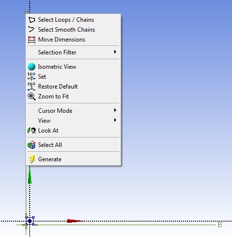
You can right click on the dimension and select Move Dimensions and move the dimensions closer to the cross section. The cross section will be easier to see if you click on the zoom to fit tool |

Assign the Cross Section with the Line Body
...
Verify Geometry
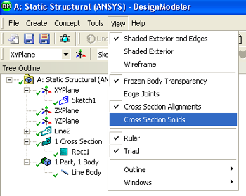
At this point the specified geometry can be checked in order to make sure all has gone well; Click on View > Cross Section Solids, as shown below;
If you click on the 1 Cross Section, 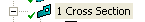 , in the Tree Outline and then click on the light blue dot,
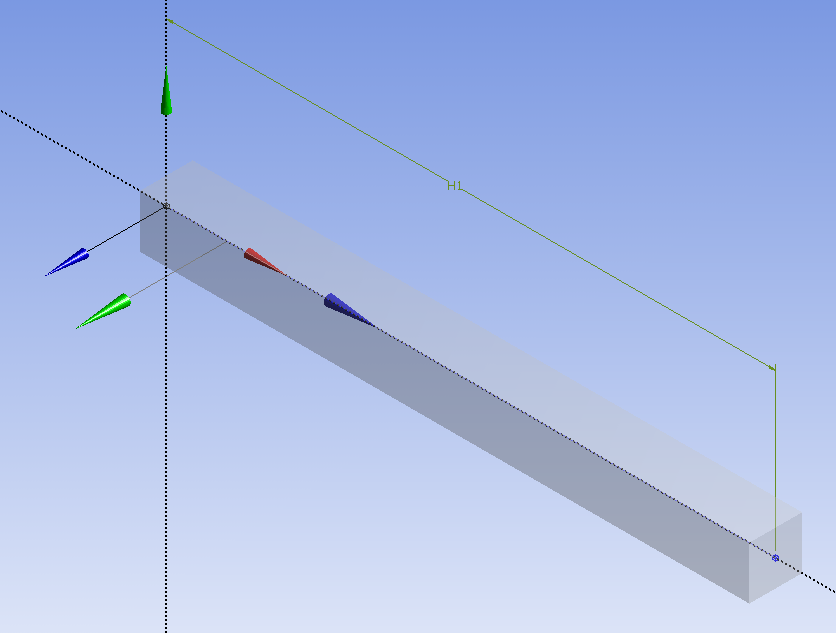
  , you should now see a three dimensionally rendered beam in an isometric view;
At this point, the Design Modeler window can be closed. Don't worry - your work will be saved.