 Sign-up for free online course on ANSYS simulations!
| Panel |
|---|
| Wiki Markup |
| {panel}
[Problem Specification|FLUENT - Laminar Pipe Flow Problem Specification]\\ [1. |FLUENT - Laminar Pipe Flow Step 1]\\ {color:#ff0000}{*}
Geometry Solution |
| Note | ||
|---|---|---|
| ||
We are working on updating this part of the tutorial. Please come back soon. |
Step 2: Geometry
Since our problem involves fluid flow, we will select the FLUENT component on the left panel.
Left click (and hold) on Fluid Flow (FLUENT), and drag the icon into the empty space in the Project Schematic. Here's what you get:
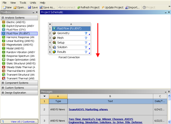
Since we selected Fluid Flow(FLUENT), each cell of the system corresponds to a step in the process of performing CFD analysis using FLUENT. Rename the project to Laminar Pipe.
We will work through each step from top down to obtain the solution to our problem.
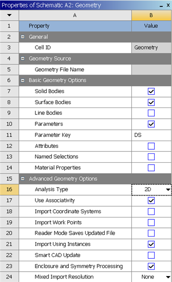
In the Project Schematic of the Workbench window, right click on Geometry and select Properties. You will see the properties menu on the right of the Workbench window. Under Advance Geometry Options, change the Analysis Type to 2D.
In the Project Schematic, double left click on Geometry to start preparing the geometry. After you launch the web tutorials and FLUENT, you will have to drag the browser window to the width of the largest image (about 350 pixels). to make best use of screen real estate, move the windows around and resize them so that you approximate
| newwindow | ||||
|---|---|---|---|---|
| ||||
https://confluence.cornell.edu/download/attachments/111221570/ScreenOrientation.PNG |
...
At this point,
...
a
...
new
...
window,
...
ANSYS
...
Design
...
Modeler
...
will
...
be
...
opened.
...
You
...
will
...
be
...
asked
...
to
...
select
...
desired
...
length
...
unit.
...
Use
...
the
...
default
...
meter
...
unit
...
and
...
click
...
OK
...
.
Creating a Sketch
Start by creating a sketch on the XYPlane. Under Tree Outline, select XYPlane, then click on Sketching right before Details View. This will bring up the Sketching Toolboxes.
| newwindow | ||||
|---|---|---|---|---|
| ||||
https://confluence.cornell.edu/download/attachments/123547957/Select+Sketching+Toolboxes.gif |
Click on the +Z axis on the bottom right corner of the Graphics window to have a normal look of the XY Plane.
| newwindow | ||||
|---|---|---|---|---|
| ||||
{newwindow}\\ Click on the {color:#660099}{*}_\+Z{_}{*}{color} axis on the bottom right corner of the {color:#660099}{*}{_}Graphics{_}{*}{color} window to have a normal look of the XY Plane. \\ \\ {newwindow:Click Here for Select Normal View Demo}https://confluence.cornell.edu/download/attachments/111221570/Select+Normal+View.gif{newwindow} In the Sketching toolboxes, select {color:#660099}{*}{_}Rectangle{_}{*}{color}. In the {color:#660099}{*}{_}Graphics{_}{*}{color} window, create a rough Rectangle from starting from the origin in the positive XY direction (Make sure that you see a letter P at the origin before you start dragging the rectangle. The letter P at the origin means the geometry is constrained at the origin.) \\ \\ \\ You should have something like this: \\ !pipe geometry.png! Note: You do not have to worry about geometry for now, we can dimension them properly in the later step. h4. Dimensions and Constraints Now we will specify the appropriate dimensions and constraints. Below is the summary of geometry of the pipe: <\!-\- /\* Font Definitions \*/ @font-face {font-family:"Cambria Math"; panose-1:2 4 5 3 5 4 6 3 2 4; mso-font-charset:0; mso-generic-font-family:roman; mso-font-pitch:variable; mso-font-signature:-1610611985 1107304683 0 0 415 0;} @font-face {font-family:Calibri; panose-1:2 15 5 2 2 2 4 3 2 4; mso-font-charset:0; mso-generic-font-family:swiss; mso-font-pitch:variable; mso-font-signature:-520092929 1073786111 9 0 415 0;} /\* Style Definitions \*/ p.MsoNormal, li.MsoNormal, div.MsoNormal {mso-style-unhide:no; mso-style-qformat:yes; mso-style-parent:""; margin-top:0in; margin-right:0in; margin-bottom:10.0pt; margin-left:0in; line-height:115%; mso-pagination:widow-orphan; font-size:11.0pt; font-family:"Calibri","sans-serif"; mso-ascii-font-family:Calibri; mso-ascii-theme-font:minor-latin; mso-fareast-font-family:Calibri; mso-fareast-theme-font:minor-latin; mso-hansi-font-family:Calibri; mso-hansi-theme-font:minor-latin; mso-bidi-font-family:"Times New Roman"; mso-bidi-theme-font:minor-bidi;} .MsoChpDefault {mso-style-type:export-only; mso-default-props:yes; mso-ascii-font-family:Calibri; mso-ascii-theme-font:minor-latin; mso-fareast-font-family:Calibri; mso-fareast-theme-font:minor-latin; mso-hansi-font-family:Calibri; mso-hansi-theme-font:minor-latin; mso-bidi-font-family:"Times New Roman"; mso-bidi-theme-font:minor-bidi;} .MsoPapDefault {mso-style-type:export-only; margin-bottom:10.0pt; line-height:115%;} @page Section1 {size:8.5in 11.0in; margin:1.0in 1.0in 1.0in 1.0in; mso-header-margin:.5in; mso-footer-margin:.5in; mso-paper-source:0;} div.Section1 {page:Section1;} \--> Vertex 2: |
In the Sketching toolboxes, select Rectangle. In the Graphics window, create a rough Rectangle from starting from the origin in the positive XY direction (Make sure that you see a letter P at the origin before you start dragging the rectangle. The letter P at the origin means the geometry is constrained at the origin.)
You should have something like this:
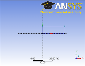
Note: You do not have to worry about geometry for now, we can dimension them properly in the later step.
Dimensions and Constraints
Now we will specify the appropriate dimensions and constraints. Below is the summary of geometry of the pipe:
Vertex 2: (0,0.1,0)
...
Vertex
...
3:
...
(8,0.1,0)
...
Vertex
...
4:
...
(8,0,0)
...
Under Sketching Toolboxes, select Dimensions tab, use the default dimensioning tools. Dimension the geometry as shown:
insert geometry dimension
Under Details View on the lower left corner, input the value for dimension appropriately.
V1: 8 m
H2: 0.1 m
Now we can constraint the lower rectangle with the top of the rectangle which has been properly dimensioned. Click Constraints tab, select Equal Length. Click the appropriate top and bottom edge and set them to be of equal length.
Now that we have the sketch done, we can create a surface for this sketch.
Concept>Surfaces From Sketches
This will create a new surface SurfaceSK1. Under Details View, select Sketch1 as Base Objects and click Apply. Finally click Generate to generate the surface.
Go to Step 3: Mesh