 Sign-up for free online course on ANSYS simulations!
...
| Note | ||
|---|---|---|
| ||
We are working on updating this part of the tutorial. Please come back soon. |
Step 2: Geometry
We'll now create a mesh on the rectangular face with 100 divisions in the axial direction and 5 divisions in the radial direction. We'll first mesh the four edges and then the face. The desired grid spacing is specified through the edge mesh.
Mesh Edges
Operation Toolpad > Mesh Command Button  > Edge Command Button
  > Mesh Edges
Shift-click or bring up the Edge List window and select both the vertical lines. If this is difficult, one can zoom in on an edge by holding down the Ctrl button, clicking and dragging the mouse to specify an area to zoom in on, and releasing the Ctrl button. To return to the main view, click on the Global Control Toolpad > Fit to Window Button again. You can also hold down Ctrl and double-click in the window to zoom out to a fitting window. To pan the view, hold down the middle mouse button and drag the mouse.
Once a vertical edge has been selected, select Interval Count from the drop down box that says Interval Size in the Mesh Edges Window. Then, in the box to the left of this combo box, enter 5 for the interval count.

Click Apply. Nodes appear on the edges showing that they are divided into 5.

...
Since our problem involves fluid flow, we will select the FLUENT component on the left panel.
Left click (and hold) on Fluid Flow (FLUENT), and drag the icon into the empty space in the Project Schematic. Here's what you get:
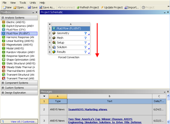
Since we selected Fluid Flow(FLUENT), each cell of the system corresponds to a step in the process of performing CFD analysis using FLUENT. Rename the project to Laminar Pipe.
We will work through each step from top down to obtain the solution to our problem.
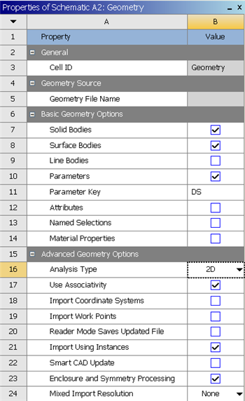
In the Project Schematic of the Workbench window, right click on Geometry and select Properties. You will see the properties menu on the right of the Workbench window. Under Advance Geometry Options, change the Analysis Type to 2D.
In the Project Schematic, double left click on Geometry Wiki Markup to start preparing the geometry. After you launch the web tutorials and FLUENT, you will have to drag the browser window to the width of the largest image (about 350 pixels). to make best use of screen real estate, move the windows around and resize them so that you approximate {new window:this screen arrangement}
...
https://confluence.cornell.edu/download/attachments/
...
111221570/
...
Repeat the same process for the horizontal edges, but with an interval count of 100.
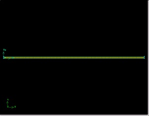
Now that the edges are meshed, we are ready to create a 2-D mesh for the face.
Mesh Face
Operation Toolpad > Mesh Command Button > Face Command Button  > Mesh Faces
Shift left-click on the face or use the up arrow next to Faces to select the face. Click Apply.
...
ScreenOrientation.PNG{newwindow}
...
At this point, a new window, ANSYS Design Modeler will be opened. You will be asked to select desired length unit. Use the default meter unit and click OK.
Go to Step 3: Mesh
See and rate the complete Learning Module
...