 Sign-up for free online course on ANSYS simulations!
| Include Page | ||||
|---|---|---|---|---|
|
| Include Page | ||||
|---|---|---|---|---|
|
Model Setup
Specify Boundary Value Problem
| HTML |
|---|
<iframe width="560" height="315" src="https://www.youtube.com/embed/VtulnpTDax0" frameborder="0" allow="accelerometer; autoplay; encrypted-media; gyroscope; picture-in-picture" allowfullscreen></iframe> |
Go to Step 5: Numerical Solution
Go to all FLUENT Learning Modules
| Panel |
|---|
Author: Rajesh Bhaskaran, John Singleton, Cornell University Problem Specification |
| Note | ||
|---|---|---|
| ||
This page of this tutorial is currently under construction. Please check back soon. |
| Info | ||
|---|---|---|
| ||
Click here for the FLUENT 6.3.26 version. |
Step 4: Setup (Physics)
...
Launch Fluent
...
https://confluence.cornell.edu/download/attachments/118475240/DoublePrecision_Full.png...
Check and Display Mesh
...
https://confluence.cornell.edu/download/attachments/118771050/MeshDispMenu_Full.png...
Define Solver Properties
...
https://confluence.cornell.edu/download/attachments/118771050/EnergyModel_Full.png...
https://confluence.cornell.edu/download/attachments/118771050/ViscModel_Full.png...
Define Governing Equations
Problem Setup > Models > Energy
Use the default and click OK.
Problem Setup > Models > Viscous
Select Laminar under Model and click Edit.
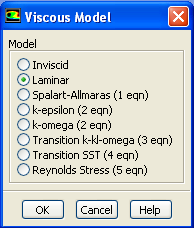
We want to leave the default value so you can click Cancel.
Problem Setup > Materials
Double click air or select it and click Create/Edit. Make sure air is selected under Fluid Materials. Set Density to 1.00 and Viscosity to 1e-4 so that we can get Re of 1e4.
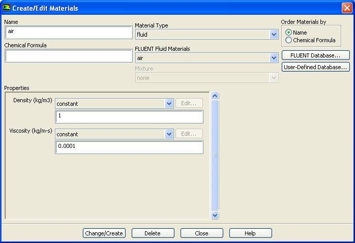
Higher Resolution Image
Click Change/Create.
Define Boundary conditions
Problem Setup > Boundary Conditions
Set the inlet boundary type to velocity-inlet. Then click Set...Set the velocity magnitude to 1 m/s. Set the outlet type to pressure-outlet boundary. Use gauge pressure of 0 Pa.Use the default value of wall for the center line. Set the far field to symmetry boundary type. Symmetry boundary condition means that the component normal to the wall is zero.
Problem Setup > Boundary Conditions
> Operating Conditions
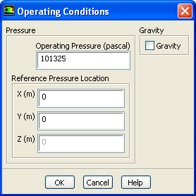
Use the default value. Click OK.
Go to Step 5: Solution