 Sign-up for free online course on ANSYS simulations!
...
| Include Page | ||||
|---|---|---|---|---|
|
| Include Page | |
|---|---|
|
...
| Panel |
|---|
Author: Rajesh Bhaskaran, Cornell University Problem Specification |
| Info | ||
|---|---|---|
| ||
Click here for the FLUENT 6.3.26 version. |
Step 4: Setup (Physics)
If you have skipped the previous mesh generation steps 1-3, you can download the mesh by right-clicking on this plateBL.msh. Save the file as plateBL.msh. Launch FLUENT.
Start > Programs > ANSYS 12.1 > Fluid Dynamics > FLUENT
Select 2ddp (2D, double-precision version) from the list of options and click Run.
Analyze Mesh
First, we check the Mesh to make sure that there are no errors.
Problem Setup > General > Mesh > Check
Any errors in the Mesh would be reported at this time. Check the output and make sure that there are no errors reported.
Main Menu > Mesh > Info > Size
How many cells and nodes does the Mesh have? You can check this in the graphics window where the mesh should be displayed. If it is not, you can display the mesh by going to
Problem Setup > General > Mesh > Display
Define Governing Equations
Problem Setup > Models > Energy
Use the default and click OK.
Problem Setup > Models > Viscous
Select Laminar under Model and click Edit.
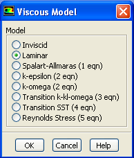
We want to leave the default value so you can click Cancel.
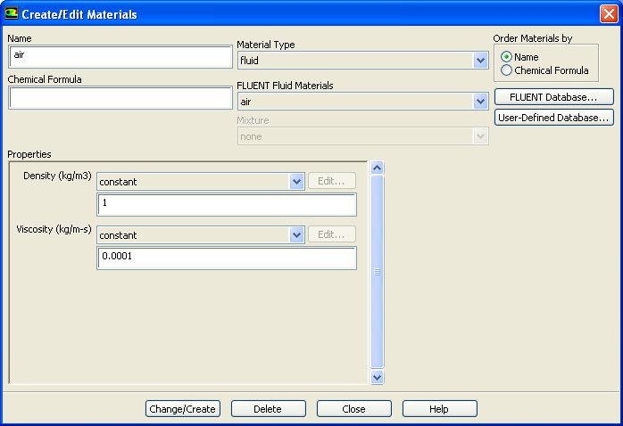
Problem Setup > Materials
Double click air or select it and click Create/Edit. Make sure air is selected under Fluid Materials. Set Density to 1.00 and Viscosity to 1e-4 so that we can get Re of 1e4.
Higher Resolution Image
Click Change/Create.
Define Boundary conditions
Problem Setup > Boundary Conditions
Set the inlet boundary type to velocity-inlet. Then click Set...Set the velocity magnitude to 1 m/s. Set the outlet type to pressure-outlet boundary. Use gauge pressure of 0 Pa.Use the default value of wall for the center line. Set the far field to symmetry boundary type. Symmetry boundary condition means that the component normal to the wall is zero.
Problem Setup > Boundary Conditions
> Operating Conditions
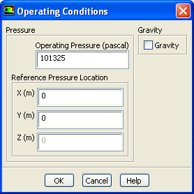
Use the default value. Click OK.
|
Model Setup
Specify Boundary Value Problem
| HTML |
|---|
<iframe width="560" height="315" src="https://www.youtube.com/embed/VtulnpTDax0" frameborder="0" allow="accelerometer; autoplay; encrypted-media; gyroscope; picture-in-picture" allowfullscreen></iframe> |