 Sign-up for free online course on ANSYS simulations!
...
Using ANSYS, determine the mechanical response due to a load of 100 lbf applied vertically downward at the end of the pedal shaft as shown in the figure below. Assume that the crank is attached rigidly to a fixed shaft fitted into the hole near the left end of the crank. This means you can constrain the surface of the left hole in X, Y and Z directions as indicated below. 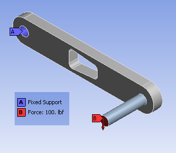
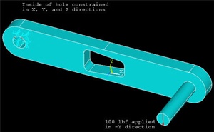
Calculate the deflection, strain and stress distributions in the crank/pedal shaft combination for this loading condition. Use the ANSYS results to evaluate the degree of stress concentration in the vicinity of the cut-out in the crank geometry.
...