 Sign-up for free online course on ANSYS simulations!
...
The following info should appear (your number of cells might be slightly different because of slight different mesh criteria used):
To view the grid we first need to create a plane that cuts our 3D model in half (otherwise it would be too hard to see a good profile of the mesh). To do this we go into:
...
Choose Pressure Based under Solver, Absolute under Velocity Formulation, Green-Gauss Node Based under Gradient Option, Unsteady under Time , 2nd-Order Implicit under Unsteady Formulation, and Superficial Velocity under Porous Formulation. (INSERT PIC) 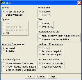
Main Menu > Define > Models > Viscous
...
The default values are the ones that we are going to use so we do not need to changeanything here. These are the values that we specified under Problem Specification.
Click Change/Create. Close the window.
...
For all flows, FLUENT uses gauge pressure internally. Any time an absolute pressure is needed, it is generated by adding the operating pressure to the gauge pressure. We'll use the default value of 1 atm (101,325 Pa) as the Operating Pressure.
Click Cancel to leave the default in place.
...
Select Inlets and click Set. We should set Velocity Specification Method to Components, and set X-velocity to 2.7754. In the Turbulence Area, we should set Specification Method to Intensity and Length Scale, and set Turbulent Intensity to 1.
All other Boundary Conditions have been set during the meshing process so nothing else should be modified here.
...