 Sign-up for free online course on ANSYS simulations!
...
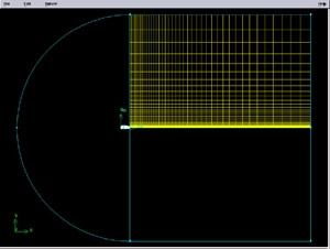
The meshed face should look as follows:
 (Click picture for larger image)
| newwindow | ||||
|---|---|---|---|---|
| ||||
Next mesh face rect2 in a similar fashion. The following table shows the parameters to use for the different edges:
...
The resultant mesh should be symmetric about CG as shown in the figure below.
 (Click picture for larger image)
| newwindow | ||||
|---|---|---|---|---|
| ||||
Split Edges
Next, we will split the top and bottom edges of the airfoil into two edges so that we have better control of the mesh point distribution. Figure of the splitting edges is shown below.
...
Select the top edge of the airfoil by Shift-clicking on it. You should see something similar to the picture below:
 (Click picture for larger image)
| newwindow | ||||
|---|---|---|---|---|
| ||||
We'll use the point at x=0.3c on the upper surface to split this edge into HI and IG. To do this, enter 0.3 for x: under Global. If your c is not equal to one, enter the value of 0.3*c instead of just 0.3.For instance, if c=4, enter 1.2. From here on, whenever you're asked to enter (some factor)*c, calculate the appropriate value for your c and enter it.
You should see that the white circle has moved to the correct location on the edge.
(Click picture for larger image)
| newwindow | ||||
|---|---|---|---|---|
| ||||
Click Apply. You will see a message saying ``Edge edge.1 was split, and edge edge.3 created'' in the Transcript window.
01split_edgefull.JPG
(Click picture for larger image)
| newwindow | ||||
|---|---|---|---|---|
| ||||
Note the yellow marker in place of the white circle, indicating the original edge has been split into two edges with the yellow marker as its dividing point.
Repeat this procedure for the lower surface to split it into HJ and JG. Use the point at x=0.3c on the lower surface to split this edge.
...
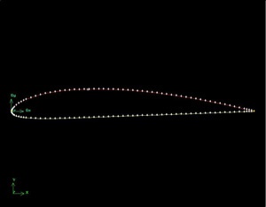
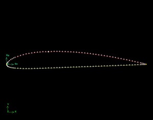
Mesh the face. The resultant mesh is shown below.
02face3full.jpg
(Click picture for larger image)
| newwindow | ||||
|---|---|---|---|---|
| ||||
Go to Step 3: Specify Boundary Types in GAMBIT
...