 Sign-up for free online course on ANSYS simulations!
| Wiki Markup |
|---|
{alias:curvedbeam}
{panel}
|
| Panel |
Author: Rajesh Bhaskaran, CornellUniversityProblem Specification 1. University {color:#ff0000}{*}Problem Specification{*}{color} [1. Start-up and preliminary set-up |ANSYS - 3D Curved Beam step 1] [2. Specify element type andconstants constants|ANSYS - 3D Curved Beam step 2] [3. Specify materialproperties properties|ANSYS - 3D Curved Beam step 3] [4. Specifygeometry geometry|ANSYS - 3D Curved Beam step 4] [5. Meshgeometry geometry|ANSYS - 3D Curved Beam step 5] [6. Specify boundaryconditions conditions|ANSYS - 3D Curved Beam step 6] [7. Solve! \!|ANSYS - 3D Curved Beam step 7] [8. Postprocess theresults results|ANSYS - 3D Curved Beam step 8] [9. Validate theresults |
Problem Specification
The problem considered here is the curved beam of uniform trapezoidal cross-section in example 6.15 of Cook et al. The beam is bent in its own plane by moments M. The problem is not axisymmetric because displacements have circumferential as well as radial and axial components. So we use 3D solid elements rather than axisymmetric elements. The geometry can nevertheless be described in cylindrical coordinates.
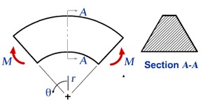
We would like to obtain the stresses for the trapezoidal cross-section AA shown above. Stresses in the curved beam do not vary with θ, so we can reduce the model and analyze only a typical slice between two closely spaced radial planes as shown below. The angle between AB and CD is taken to be 5 deg. as suggested by Cook el al.
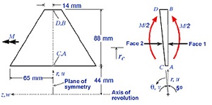
The bending moment M must be applied indirectly in the reduced model since we don't know a priori the circumferential stress distribution it produces on the cross-section. Instead, we'll prescribe displacements such that radial plane sections remain plane and a pure moment load acts on the model i.e. no net force acts on it. The moment M can be computed from the stress distribution on the cross-section obtained from FEA. Stresses scale linearly with the applied moment. So the stresses associated with a prescribed moment Mp can be obtained by multiplying the computed stresses by the ratio Mp/M.
The z-constant plane containing A,B,C and D is a symmetry plane. So only half the cross-section needs to be modeled.
Boundary Conditions
The nodal d.o.f. in the radial (u), circumferential (v), and axial (w) directions are constrained as follows:
Face 1 | Face 2 |
u=0 at node A | . |
v=0 at all nodes | v=0.0001(rc-r)at all nodes |
w=0 along AB | w=0 along CD |
All remaining d.o.f. are unrestrained. Setting u=0 at A prevents rigid body motion in the r-direction. Setting v=0 on face 1 nodes prevents circumferential motion of face 1. Setting w=0 on ABCD imposes symmetry about the middle r-θ plane. The above BC on face 2 nodes causes face 2 to remain plane as it rotates about a z-parallel axis at r=rc. The factor 0.0001 is arbitrarily chosen. At the outset, the appropriate value of rc is not known. The right value of rc will give a pure bending load so that the radial reaction RA at node A is zero. Two preliminary FE analysis with guess values of rc=60mm and rc=70mm were done. The respective RA values turn out to be 2001N and 357N. By linear extrapolation, RA=0 when rc=72.2mm. So we'll use rc=72.2mm in our analysis. (Since this is a pedagogical exercise, I've decided to be nice and give you the rc value to use. In the real world, you'd of course have to figure it out yourself).
Go to Step 1: Start-up and preliminary set-up
See and rate the complete Learning Module
...
 results|ANSYS - 3D Curved Beam step 9]
{panel}

h2. Problem Specification

The problem considered here is the curved beam of uniform trapezoidal         cross-section in example 6.15 of Cook et         al. The beam is bent in its own plane by moments M. The problem is          not axisymmetric because displacements have circumferential as well as          radial and axial components. So we use 3D solid elements rather than axisymmetric          elements. The geometry can nevertheless be described in cylindrical coordinates.

!beam2.jpg!

We would like to obtain the stresses for the trapezoidal cross-section          AA shown above. Stresses in the curved beam do not vary with θ, so          we can reduce the model and analyze only a typical slice between two closely          spaced radial planes as shown below. The angle between AB and CD is taken          to be 5 deg. as suggested by Cook el al.

!beam_nomesh.jpg!

The bending moment _M_ must be applied indirectly in the reduced          model since we don't know _a priori_ the circumferential stress distribution          it produces on the cross-section. Instead, we'll prescribe _displacements_ such that radial plane sections remain plane and a pure moment load acts          on the model i.e. no net force acts on it. The moment _M_ can be          computed from the stress distribution on the cross-section obtained from          FEA. Stresses scale linearly with the applied moment. So the stresses          associated with a prescribed moment _M{_}{_}{~}p{~}_ can be obtained          by multiplying the computed stresses by the ratio _M{_}{_}{~}p{~}{_}_/M_.

The z-constant plane containing A,B,C and D is a symmetry plane. So only          half the cross-section needs to be modeled.

h4. Boundary Conditions

The nodal d.o.f. in the radial (u), circumferential (v), and axial (w)          directions are constrained as follows:
| *Face                1* | *Face                2* |
| _u_=0 at node A | . |
| _v_=0 at all nodes | _v_=0.0001(r{~}c~\-r)at all nodes |
| _w_=0 along AB | _w_=0 along CD |
All remaining d.o.f. are unrestrained. Setting u=0 at A prevents rigid          body motion in the r-direction. Setting v=0 on face 1 nodes prevents circumferential          motion of face 1. Setting w=0 on ABCD imposes symmetry about the middle          r-θ plane. The above BC on face 2 nodes causes face 2 to remain plane          as it rotates about a z-parallel axis at r=r{~}c~. The factor 0.0001          is arbitrarily chosen. At the outset, the appropriate value of r{~}c~ is not known. The right value of r{~}c~ will give a pure bending          load so that the radial reaction R{~}A~ at node A is zero. Two          preliminary FE analysis with guess values of r{~}c~=60mm and r{~}c~=70mm          were done. The respective R{~}A~ values turn out to be 2001N and          357N. By linear extrapolation, R{~}A~=0 when r{~}c~=72.2mm.          So we'll use r{~}c~=72.2mm in our analysis. (Since this is a pedagogical          exercise, I've decided to be nice and give you the r{~}c~ value          to use. In the real world, you'd of course have to figure it out yourself).

Go to [Step 1: Start-up and preliminary set-up|ANSYS - 3D Curved Beam step 1]

[See and rate the complete Learning Module|ANSYS - 3D Curved Beam]

[Go to all ANSYS Learning Modules|ANSYS Learning Modules] |