 Sign-up for free online course on ANSYS simulations!
...
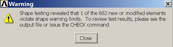
Elements that exceed shape warning limits can lead to degraded accuracy. Here it is a small minor concern since only 1 element out of 682 is causing the warning. So it is reasonable to press on. In general, it is always a good idea to pay close attention to the warnings and understand their effect on your solution. As a veteran in these things, I can attest that ignoring warnings can come back to bite you in incovenient parts of the anatomy. Close the warning window. Feel free to experiment with the mesh tool parameters.
Bring up the MeshTool again, and now Set the mesh type to SOLID45. Under Global Size Controls, click Set. We want four layers of mesh elements to span the thickness of the volumecrank, so we will enter a SIZE Element edge length of (0.5 / 4) = 0.125. Click OK. Since we had created a MESH200 on the face of the crank, we can now simply sweep that mesh across the volume. Choose Volumes with a Shape Hex/Wedge to be meshedWe will now sweep, i.e. extrude, the surface meshes created above across the corresponding volumes. Select Volumes to be meshed with a Hex shape using the Sweep option as shown below. Make sure Auto Src/Trg is selected and click Sweep. Now all we have to do is pick the crank volume, and ; this will automatically pick a source (Src) surface and sweep/extrude it to a traget (Trg) surface.
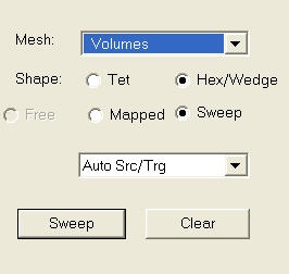
Click Sweep and Pick All to sweep-mesh both volumes. ANSYS will extend our previous mesh surface meshes across the volumecorresponding volumes.
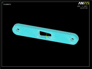
You can always see the rest of your model by selecting Utility Menu > Plot > Volumes
Now repeat the whole procedure with the crank shaft (starting from the top of step 5). Remember that the shaft element size must be the same as the crank so that the shaft elements and crank elements in the hole line up. (You can ignore any errors that may pop up regarding element size. ANSYS is complaining because the shape of some of the quadrilateral elements in high stress areas have a non-ideal element shape) Your final meshed model should look like the following. We're almost ready to solve the problem.
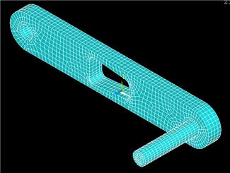
ANSYS issues a warning that 5 out of 3986 elements violate shape warning limits. Since the number of "bad" elements is small, this is a minor concern and we'll press on. But keep in mind that what we'll obtain is a reasonable first-cut solution but it will not be the final word. For that, you'll have to show that the solution is independent of the mesh. Close the warning window.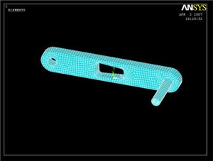
Save Your Work
Toolbar > SAVE_DB
Go to Step 6: Specify boundary conditions
...