 Sign-up for free online course on ANSYS simulations!
...
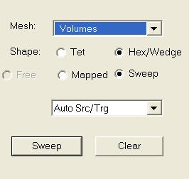
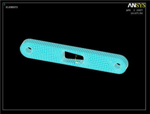
Bring up the MeshTool again, and now Set the mesh type to SOLID45. Under Global Size Controls, click Set. We want four layers of mesh elements to span the thickness of the volume, so we will enter a SIZE Element edge length of (0.5 / 4) = 0.125. Click OK. Since we had created a MESH200 on the face of the crank, we can now simply sweep that mesh across the volume. Choose Volumes with a Shape Hex/Wedge to be meshed. Make sure Auto Src/Trg is selected and click Sweep. Now all we have to do is pick the crank volume, and ANSYS will extend our previous mesh across the volume.
You can always see the rest of your model by selecting Utility Menu > Plot > Volumes.
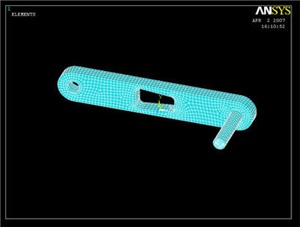
Now repeat the whole procedure with the crank shaft (starting from the top of step 5). Remember that the shaft element size must be the same as the crank so that the shaft elements and crank elements in the hole line up. (You can ignore any errors that may pop up regarding element size. ANSYS is complaining because the shape of some of the quadrilateral elements in high stress areas have a non-ideal element shape) Your final meshed model should look like the following. We're almost ready to solve the problem.
Save Your Work
Toolbar > SAVE_DB
Go to Step 6: Specify boundary conditions
See and rate the complete Learning Module
...