 Sign-up for free online course on ANSYS simulations!
...
The node and element numbers will now appear in the Graphics window.
List Forces in Truss Members
...
Main Menu > General Postproc > List Results > Element Solution
From the list, under Element Solution, select All Available force items. Click OK.
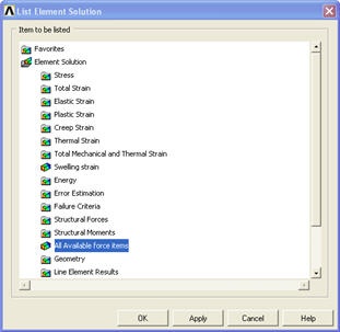
This brings up a window listing the forces that the elements apply on each of their nodes:
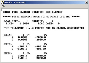
These element forces reported by ANSYS are forces ON its environment BY the element, not the converse. For example, Element 2 (or member AB) applies a force of 1500 N in the x-direction and 800 N in the negative y-direction on node 1 (or pin A). This means that the total force in AB is . The resultant acts from A to B i.e. the member is pulling on pin A. So it must be in tension. Similarly, the force in Element 1 (AC) is 2000 N (tension) and in Element 3 (BC) is 2500 N (compression). Note that your node and element numbers might be different from the above since they depend on the order in which the lines were created.
Close the PRESOL Command window.
...
Bring up the help page for LINK1 element:
...
The figure at the top of the LINK1 help page shows that the x-direction in the element coordinate system is along the element. So MFORX is basically the axial force in the element.
...