 Sign-up for free online course on ANSYS simulations!
Step 9: Validate the results
It is very important that you take the time to check the validity of your solution. This section leads you through some of the steps you can take to validate your solution.
Simple Checks
Does the deformed shape look reasonable and agree with the applied boundary conditions? We checked this in step 8.
...
So the reaction cancels out the applied force in the x-direction. Similarly, you can check that this is true in the y-direction also.
Refine Mesh
Let's repeat the calculations on a mesh with overall element size level under SmartSize set to 4 instead of 5 and compare the results on the two meshes. Delete the current mesh:
...
Select Nodal Solution > Stress > von Mises stress and click OK
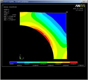
Compare this with the von Mises contours for the previous mesh:
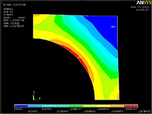
The two results compare well with the finer mesh contours being smoother as expected. Compare the maximum stress and displacement values:
...
The maximum displacement value changes by less than 1% and the maximum von Mises stress value by less than 3%. This indicates that the meshes used provide adequate resolution.
Exit ANSYS
Utility Menu > File > Exit
Select Save Everything and click OK.
Reference
Cook, R.D., Malkus, D.S., Plesha, M.E., and Witt, R.J., Concepts and Applications of Finite Element Analysis, Fourth Edition, John Wiley and Sons, Inc., 2002.
Go to Problem Set 1