 Sign-up for free online course on ANSYS simulations!
Step 6: Specify boundary conditions
Next, we step up to the plate to define the displacement constraints and loads. Recall that in ANSYS terminology, the displacement constraints are also "loads". As in the truss tutorial, we'll apply the loads to the geometry rather than the mesh. That way we won't have to reapply the loads on changing the mesh.
Apply Symmetry Boundary Conditions
ANSYS provides the option of applying a "symmetry boundary condition" along lines of symmetry.
...
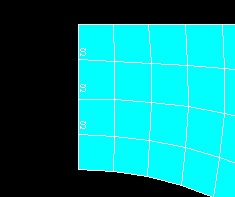
Select the straight lines corresponding to the left and bottom edges (which are the lines of symmetry for this problem) by clicking on them. Click OK in the pick menu. The symbol s appears along these lines indicating that the symmetry B.C. is applied along these lines.
Apply Pressure
Main Menu > Preprocessor > Loads > Define Loads > Apply > Structural > Pressure > On Lines
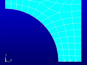
Select the circular arc and click OK. This brings up the Apply Pressure on Lines menu. Enter p for Value and click OK. A single red arrow denotes the pressure and the direction in which it is acting.
Check Loads
Let's check that the displacement constraints have been applied correctly.
Utility Menu > List > Loads > DOF constraints > On All Lines
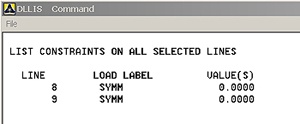
Symmetry BCs are applied on lines 8 and 9. Turn on line numbering:
...
Turn off line numbering: Utility Menu > PlotCtrls > Numbering. Turn off Line numbers and click OK.
Save Your Work
Toolbar > SAVE_DB
Go to Step 7: Solve