 Sign-up for free online course on ANSYS simulations!
...
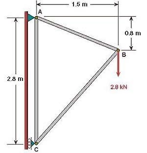
Since we are using the 2D Spar element, we can represent each truss member by a line. A line can be created by joining two keypoints (ANSYS terminology for vertices). So we'll need three keypoints, located at A, B and C in the figure below. We'll locate the origin of the coordinate system at C and number the keypoints at A, B and C as 1, 2 and 3, respectively.
Create Keypoints
Main Menu > Preprocessor > Modeling > Create > Keypoints > In Active CS
The active CS (i.e. Coordinate System) is the global Cartesian system by default and we'll work only in this coordinate system in our friendly introduction. ANSYS offers the capability to switch between various types of coordinate systems which will be necessary when you move on to solving super-duper problems.
...
Enter 1 for Keypoint number
Enter 0 for X and 2.8 for Y
(The Z value defaults to zero)
Click Apply (which accepts the input and then brings back the dialog box for further input)
...
Enter 2 for Keypoint number
Enter 1.5 for X and 2.0 for Y
Click Apply
Enter 3 for Keypoint number
Enter 0 for X and 0 for Y
Click OK (which accepts the input and then closes the dialog box)
...
The keypoints will now be displayed in the Graphics window along with a triad that indicates the origin of the coordinate system (coincident with keypoint 3 in our case) and the axes.
Check Keypoints
To check if the keypoints have been created correctly:
Utility Menu > List > Keypoints > Coordinates only
This brings up a window listing the coordinates and rotation angles for the keypoints. Verify that you have the following:
...