 Sign-up for free online course on ANSYS simulations!
...
Now we can proceed to create the geometry for radius of influence. Since both the cylinder and radius of influence is of same shape. We can create the radius of influence by copying and scaling up the cylinder.
Create arc of radius 4 from -45 to 45 deg. Then create another arc from 45 to 45 deg.
Operation Toolpad > Geometry Command Button ![]() > Edge Command Button
> Edge Command Button ![]() > Create Edge
> Create Edge ![]() > Arc
> Arc ![]() >
> 
Finally split the edge at 90 and -90 deg.
Operation Toolpad > Geometry Command Button ![]() > Edge Command Button
> Edge Command Button ![]() > Move/Copy Edges
> Move/Copy Edges 
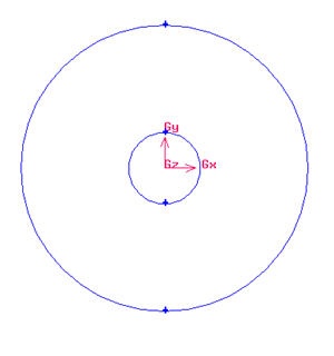
Select the cylinder edges. Make sure that the Copy is checked. Under Operation, select Scale. Next to Factor, enter a value of 4. This means that the radius of influence we create will be 4 times the size of the cylinder.
The current geometry should look like this:
editor NOTE (duplicate vertices created...)
...
Split Edge ![]()
Remember to change the coordinate Type to Cylindrical.
Split Edge at Outer Boundary
For regular mesh, each edge has its opposite edge. Because of this, we can use projection method on the outer boundary to create the edge associated with the Radius of Influence edges.
Operation Toolpad > Geometry Command Button  > Vertex Command Button
  >
> 
Create Upstream Boundary
We will first create the semi-circle upstream boundary.
...