 Sign-up for free online course on ANSYS simulations!
...
Operation Toolpad > Geometry Command Button ![]() > Edge Command Button
> Edge Command Button ![]() > Move/Copy Edges
> Move/Copy Edges 
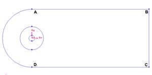
Select the cylinder edges. Make sure that the Copy is checked. Under Operation, select Scale. Next to Factor, enter a value of 4. This mean means that the radius of influence we create will be 4 times the size of the cylinder.
...
We will first create the semi-cylinder circle upstream boundary.
Operation Toolpad > Geometry Command Button ![]() > Edge Command Button
> Edge Command Button ![]() > Create Edge
> Create Edge ![]() > Arc
> Arc ![]() >
> 
Input the following data and click apply Apply.
Radius | 10 |
Start Angle | 90 |
End Angle | -90 |
...
| Info | ||
|---|---|---|
| ||
After this operation, you You should see have this geometry up till this step.
Split Edges
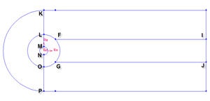
We would like to have more mesh elements at the downstream of the flow, to the right of the cylinder. To accomplish this, we would have to split some edges.
...
Label | x | y | z |
E | 2.83 | 10 | 0 |
H | 2.83 | -10 | 0 |
I | 40 | 2.83 | 0 |
J | 40 | -2.83 | 0 |
Select appropriate edge one by one. For example, to create vertex H, we have to split the bottom edge.
Operation Toolpad > Geometry Command Button ![]() > Edge Command Button
> Edge Command Button ![]() > Split Edge
> Split Edge ![]()
Then And then select the respective edges to split to for point E,H,I and J.bottom edge. Enter the coordinate value for vertex H. Do this for the rest of vertices.
Now, we will After that, split the curved edges
Label | r | t | z |
F | 4 | 45 | 0 |
G | 4 | -45 | 0 |
...
Change the coordinate Type to Cylindrical and create vertex point F and G according to the table.
Connect all Vertices
Finally, connect all the remaining vertices KL, LM, NO, OP, FI and GJ.
the The newly created vertices to form two new edges. The current geometry in Gambit should look like this:
...