 Sign-up for free online course on ANSYS simulations!
...
Select the cylinder edges. Then change the coordinate Type to Cylindrical and create a vertex by entering the angle, t as -90.
| Info | |||||||||||||||||||||||
|---|---|---|---|---|---|---|---|---|---|---|---|---|---|---|---|---|---|---|---|---|---|---|---|
| |||||||||||||||||||||||
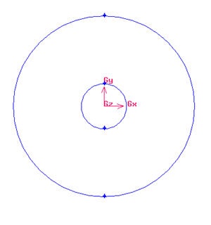
Create Radius of InfluenceNow we can proceed to create the geometry for radius of influence. Since both the cylinder and radius of influence is of same shape. We can create the radius of influence by copying and scaling up the cylinder. Operation Toolpad > Geometry Command Button The current geometry should look like this:
editor NOTE (duplicate vertices created...) Create Farfield BoundariesCreate Upstream Boundary We will first create the semi-cylinder upstream boundary. Operation Toolpad > Geometry Command Button Input the following data and click apply.
Create Downstream Boundaries In creating downstream boundaries, we will use bottom up approach where we first create vertices and join the vertices to form edges. Create vertices with following coordinates:
Operation Toolpad > Geometry Command Button Create the vertices by entering the coordinates under Global. Click the FIT TO WINDOW button to scale the display so that you can see all the vertices. Connect AB, BC and CD to form three edges. Operation Toolpad > Geometry Command Button
|


| Info |
|---|
After this operation, you should see this geometry.
...