 Sign-up for free online course on ANSYS simulations!
...
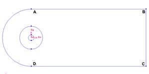
We know that we need a cylinder and farfield boundaries. We also know that there will be active regions around cylinder (call this radius of influence). Therefore we would want the area around cylinder to be of finer mesh. We also know there will be wake downstream of the flow after behind the cylinder. Therefore we also want finer mesh around that region. Figure below shows the number of faces required to make such mesh.
...
We set the geometry upstream to be short shorter because we have constant velocity most of the timeless activity around the region. We set the geometry downstream of the cylinder to be long relatively longer because we would like to capture the activity of the wake induced by the cylinder.
...
Input the following data and click apply Apply.
Radius | 1 |
Start Angle | 90 |
End Angle | 450 |
...
Operation Toolpad > Geometry Command Button ![]() > Edge Command Button
> Edge Command Button ![]() > Split Edge
> Split Edge ![]()
Select the cylinder edgeedges. Then change the coordinate Type to Cylindrical and create a vertex by entering the angle, t as -90.
...
Connect AB, BC and CD to form three edges.
Operation Toolpad > Geometry Command Button ![]() > Edge Command Button
> Edge Command Button ![]() > Create Edge
> Create Edge ![]()
| Info | ||
|---|---|---|
| ||
After this operation, you should see this geometry.
Split Edges
...
Split the edge according to the figure shown below:
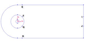
First split the straight edges
...
Change the coordinate Type to Cylindrical and create vertex point F and G according to the table.
Connect all Vertices
Finally, connect all the remaining vertices KL, LM, NO, OP, FI and GJ.
the newly created vertices to form two new edges. The current geometry in Gambit should look like this: 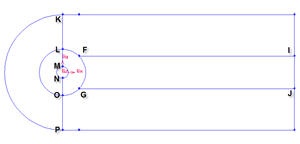
Create Faces
We can now join all the edges to form faces.
...