 Sign-up for free online course on ANSYS simulations!
...
Under Main Menu, select Solver > FLUENT 5/6 since the mesh to be created is to be used in FLUENT 6.0.
Create Cylinder
...
Let's first create the cylinder and the radius of influence. Create the cylinder using arc
...
Select the cylinder edge. Then change the coordinate Type to Cylindrical and create a vertex by entering the angle, t as -90.
Create Radius of Influence
Now we can proceed to create the geometry for radius of influence. Since both the cylinder and radius of influence is of same shape. We can create the radius of influence by copying and scaling up the cylinder.
Operation Toolpad > Geometry Command Button ![]() > Edge Command Button
> Edge Command Button ![]() > Move/Copy Edges
> Move/Copy Edges 
Select the cylinder edges. Make sure that the Copy is checked. Under Operation, select Scale. Next to Factor, enter a value of 4. This mean that the radius of influence we create will be 4 times the size of the cylinder.
editor NOTE (duplicate vertices created...)
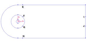
Create Farfield Boundaries
...
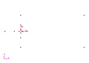
Create the vertices by entering the coordinates under Global and the label under Label:.
Click the FIT TO WINDOW button to scale the display so that you can see all the vertices. The resulting image should look like this:
Create Edges
Create the edges using the vertices created. For our model, we have two type of edges: straight edge and curved edge.
Let's first start by creating straight edges by connecting following vertices:
4-12
12-13
13-9
9-8
8-7
6-5
5-4
Operation Toolpad > Geometry Command Button > Edge Command Button > Create Edge
Create the edge 4-12 by selecting the vertex 4 followed by vertex 12. Click Apply. GAMBIT will create the edge. You will see a message saying something like "Created edge: edge.1'' in the Transcript window.
...
| title | Press "shift" + left mouse click and drag to select |
|---|
After we create all the straight edges, start creating arc by connecting the following vertices:
4-1-9
5-2-8
5-11-8
6-3-7
6-10-7
Connect AB, BC and CD to form three edges.
Operation Toolpad > Geometry Command Button ![]() > Edge Command Button
> Edge Command Button ![]() > Create Edge
> Create Edge ![]() > Arc
> Arc ![]()
Right click on the Create Edge to see more options. Select the Arc icon. (The default option is Straight)
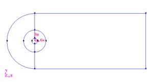
After this operation, you should see this geometry.
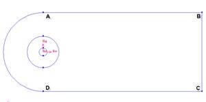
The current geometry should look like this:
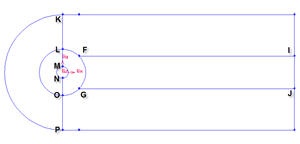
Split Edges
We would like to have more mesh elements at the downstream of the flow, to the right of the cylinder. To accomplish this, we would have to split some edges.
Split the edge according to the figure shown below: 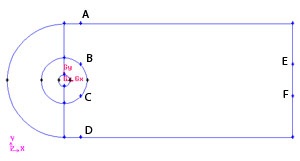
First split the straight edges
Label | x | y | z |
A E | 2.8284 83 | 10 | 0 |
D H | 2.8284 83 | -10 | 0 |
E I | 40 | 2.8284 83 | 0 |
F J | 40 | -2.8284 83 | 0 |
Operation Toolpad > Geometry Command Button ![]() > Edge Command Button
> Edge Command Button ![]() > Split Edge
> Split Edge ![]()
Then select the respective edges to split to for point AE,DH,E I and FJ.
After that, split the curved edges
Label | r | t | z |
B F | 4 | 45 | 0 |
C G | 4 | -45 | 0 |
Operation Toolpad > Geometry Command Button ![]() > Edge Command Button
> Edge Command Button ![]() > Split Edge
> Split Edge ![]()
Change the coordinate Type to Cylindrical and create vertex point B F and C G according to the table.
Finally, connect all the remaining vertices KL, LM, NO, OP, FI and GJ.
the newly created vertices to form two new edges. The current geometry in Gambit should look like this:
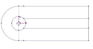
Create Faces
...