 Sign-up for free online course on ANSYS simulations!
| Panel |
|---|
Author: Yong Sheng Khoo & Rajesh Bhaskaran, Cornell University Problem Specification |
...
We know that we need a cylinder and farfield boundaries. We also know that there will be active regions around cylinder (call this radius of influence). Therefore we would want the area around cylinder to be of finer mesh. We also know there will be wake downstream of the flow after cylinder. Therefore we also want finer mesh around that region. Figure below shows the number of faces required to make such mesh.
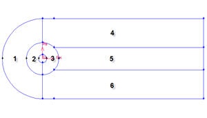
We set the geometry upstream to be short because we have constant velocity most of the time. We set the geometry downstream of the cylinder to be long because we would like to capture the activity of the wake induced by the cylinder.
Create a Working Directory
...
Now we can proceed to create the geometry for radius of influence. Since both the cylinder and radius of influence is a cylinderof same shape. We can create the radius of influence by copying the cylinder.
Operation Toolpad > Geometry Command Button ![]() > Edge Command Button
> Edge Command Button ![]() > Move/Copy Edges
> Move/Copy Edges 
First, create vertices with following coordinates:
Select the cylinder edges. Make sure that the Copy is checked. Under Operation, select Scale. Next to Factor, enter a value of 4. This mean that the radius of influence we create will be 4 times the size of the cylinder.
Create Farfield Boundaries
Create Upstream Boundary
We will first create the semi-cylinder upstream boundary.
Operation Toolpad > Geometry Command Button ![]() > Edge Command Button
> Edge Command Button ![]() > Create Edge
> Create Edge ![]() > Arc
> Arc ![]() >
> 
Input the following data and click apply.
Radius | 10 |
Start Angle | 90 |
End Angle | -90 |
Create Downstream Boundaries
In creating downstream boundaries, we will use bottom up approach where we first create vertices and join the vertices to form edges.
Create vertices with following coordinates:
Label | x | y | z |
1 | |||
Label | x | y | z |
1 | -10 | 0 | 0 |
2 | -4 | 0 | 0 |
3 | -1 | 0 | 0 |
4 | 0 | 10 | 0 |
5 | 0 | 4 | 0 |
6 | 0 | 1 | 0 |
7 | 0 | -1 | 0 |
8 | 0 | -4 | 0 |
9 | 0 | -10 | 0 |
10 | 1 | 0 | 0 |
11 | 4 | 0 | 0 |
12 | 40 | 10 | 0 |
13 2 | 40 | -10 | 0 |
To create a vertex, do the following:
Operation Toolpad > Geometry Command Button  > Edge Vertex Command Button
 > Create Edge
 ![]() Vertex
Vertex 
Create the vertices by entering the coordinates under Global and the label under Label:
...