 Sign-up for free online course on ANSYS simulations!
| Panel |
|---|
Problem Specification |
| Info | ||
|---|---|---|
| ||
If you are having trouble following written tutorial, detailed video tutorials are available here |
Step 1: Create Geometry in GAMBIT
| Info | ||
|---|---|---|
| ||
If you would prefer to skip the mesh generation steps, you can download the mesh from here and go straight to step 4. |
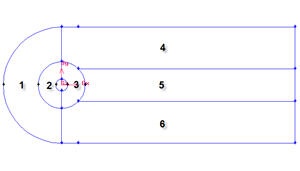
In an external flow such as the flow past a cylinder, we have to define farfield boundaries and mesh the region between the cylinder geometry and the boundaries. Farfield boundaries should be placed well away from the cylinder so that they are not under the influence of the flow around such that the boundary conditions will not affect the flow near cylinder.
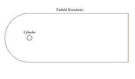
Figure above shows the geometry of such a case.
Strategy for Creating Geometry
To model this flow, we need a cylinder and farfield boundaries. We need finer meshes around the cylinder to capture the active region (call this radius of influence). Downstream of the flow, there will be wake generated by the cylinder, which requires finer mesh to better capture this phenomena. To be able to specify such regions, we split the domain into different faces as shown below.
We set the geometry upstream to be shorter because we have less activity before flow through cylinder. We set the geometry downstream of the cylinder to be relatively longer such that the boundary conditions will not affect the flow near cylinderThere are different methods in creating geometry. The most fundamental approach in creating geometry is the bottom-up vertical hierarchy approach. We will start by first creating vertices, then connecting the vertices to form edges, and finally connect the edges to form faces. Note that in 3D problems, you'll have to form a "volume" from faces. So the hierarchy of geometric objects in GAMBIT is vertices -> edges -> faces -> volumes.
Create a Working Directory
...
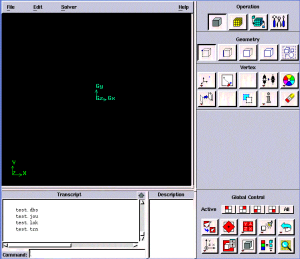
Create a new directory called cylinder and start GAMBIT from that directory by typing gambit -id cylinder at the command prompt.
Under Main Menu, select Solver > FLUENT 5/6 since the mesh to be created is to be used in FLUENT 6.0.
Create
...
First, create vertices with following coordinates:
Label | x | y | z |
1 | -10 | 0 | 0 |
2 | -4 | 0 | 0 |
3 | -1 | 0 | 0 |
4 | 0 | 10 | 0 |
5 | 0 | 4 | 0 |
6 | 0 | 1 | 0 |
7 | 0 | -1 | 0 |
8 | 0 | -4 | 0 |
9 | 0 | -10 | 0 |
10 | 1 | 0 | 0 |
11 | 4 | 0 | 0 |
12 | 40 | 10 | 0 |
13 | 40 | -10 | 0 |
Cylinder
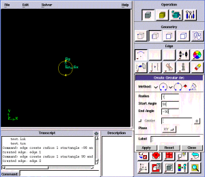
Create the cylinder using two arcs. The cylinder is created with two arc because they are going to be meshed differently. Back arc spans from -90 to 90 deg. Front arc spans from 90 to -90 deg. Both arc with radius 1.
Operation Toolpad > Geometry Command Button ![]() > Edge Command Button
> Edge Command Button ![]() > Create Edge
> Create Edge ![]() > Arc
> Arc ![]() >
> 
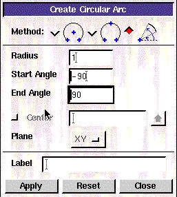
Next to Radius, enter 1. Next to Start Angle, enter -90. Next to End Angle, enter 90. Click Apply. Do the same for front arc but enter different value for angles.
| Warning | ||
|---|---|---|
| ||
(Click here for animated steps)
| Info | ||
|---|---|---|
| ||
Create Front Outer Boundary
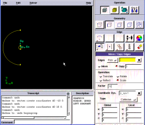
We will create the outer boundary by creating arc 10 times of the cylinder front arc. We can use copy edges and scale by 10 to create the outer boundary.
Operation Toolpad > Geometry Command Button ![]() > Edge Command Button
> Edge Command Button ![]() > Move/Copy Edges
> Move/Copy Edges 
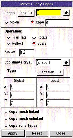
Select the front cylinder edge. Make sure that the Copy is checked. Under Operation, select Scale. Next to Factor, enter a value of 10. This means that the radius of influence we create will be 10 times the size of the cylinder. Click Apply.
(Click here for animated steps)
| Info | ||
|---|---|---|
| ||
Create Back Outer Boundary
For this part, we will start with bottom up approach where we first create vertices and then using the vertices to create edges. Create the following vertices.
Vertices | X | Y |
|---|---|---|
1 | 40 | 10 |
2 | 40 | -10 |
...
Operation Toolpad > Geometry Command Button  > Edge Vertex Command Button
 > Create Edge
 ![]() Vertex
Vertex 
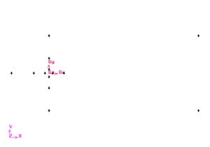
Create the vertices by entering the coordinates under Global and the label under Label:.
Click the FIT TO WINDOW button to scale the display so that you can see all the vertices. The resulting image should look like this:
Create Edges
Create the edges using the vertices created. For our model, we have two type of edges: straight edge and curved edge.
Let's first start by creating straight edges by connecting following vertices:
4-12
12-13
13-9
9-8
8-7
6-5
5-4
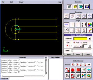
Connect the vertices to create three edges
Operation Toolpad > Geometry Command Button ![]() > Edge Command Button
> Edge Command Button ![]() > Create Edge
> Create Edge
Create the edge 4-12 by selecting the vertex 4 followed by vertex 12. Click Apply. GAMBIT will create the edge. You will see a message saying something like "Created edge: edge.1'' in the Transcript window.
![]()
| Info | ||
|---|---|---|
| ||
Following animated steps show another method in creating vertices.
| Info | ||
|---|---|---|
| ||
| Tip | ||
|---|---|---|
| ||
Do you know that by clicking and holding right mouse click and move up and down, you can zoom in and out in the graphic window? |
Create Radius of Influence
Now we can proceed to create the geometry for radius of influence. Since both the cylinder and radius of influence is of same shape.
Create arc of radius 4 from -45 to 45 deg. Then create another arc from 45 to 45 deg. After we create all the straight edges, start creating arc by connecting the following vertices:
4-1-9
5-2-8
5-11-8
6-3-7
6-10-7
Operation Toolpad > Geometry Command Button ![]() > Edge Command Button
> Edge Command Button ![]() > Create Edge
> Create Edge ![]() > Arc
> Arc ![]()
Right click on the Create Edge to see more options. Select the Arc icon. (The default option is Straight)
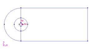
The current geometry should look like this:
Split Edges
We would like to have more mesh elements at the downstream of the flow, to the right of the cylinder. To accomplish this, we would have to split some edges.
Split the edge according to the figure shown below:
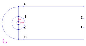
First split the straight edges
Label | x | y | z |
A | 2.8284 | 10 | 0 |
D | 2.8284 | -10 | 0 |
E | 40 | 2.8284 | 0 |
F | 40 | -2.8284 | 0 |
>
Finally split the edge at 90 and -90 deg.
Operation Toolpad > Geometry Command Button ![]() > Edge Command Button
> Edge Command Button ![]() > Split Edge
> Split Edge ![]()
Then select the respective edges to split to for point A,D,E and F.
After that, split the curved edges
...
Label
...
r
...
t
...
z
...
B
...
4
...
45
...
0
Remember to change the coordinate Type to Cylindrical.
Split Edge at Outer Boundary
For regular mesh, each edge has its opposite edge. Because of this, we can use projection method on the outer boundary to create the edge associated with the Radius of Influence edges.
...
C
...
4
...
-45
...
Operation Toolpad > Geometry Command Button > Edge Vertex Command Button ![]() > Split Edge
> Split Edge ![]()
Change the coordinate Type to Cylindrical and create vertex point B and C according to the table.
> Project Button 
Select the vertex and associated edge. Make sure to select Split edge. At the end of this, you should have 4 new vertices.
(Animated steps)
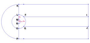
Connect all Vertices
Finally, connect all the remaining vertices KL, LM, NO, OP, FI and GJ.
Finally, connect the newly created vertices to form two new edges. The current geometry in Gambit should look like this: 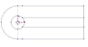
Create Faces
We can now join all the edges to form faces.
Operation Toolpad > Geometry Command Button ![]() > Face Command Button
> Face Command Button  > Form Face
This brings up the Create Face From Wireframe menu. Recall that we had selected vertices in order to create edges. Similarly, we will select edges in order to form a face.
There will be total of six faces.
(Click picture for larger image)
Create all the six faces by connecting appropriate edges.
Animated steps
We are now ready to mesh the geometry.
Go to Step 2: Mesh Geometry in GAMBIT
See and rate the complete Learning Module
...