 Sign-up for free online course on ANSYS simulations!
...
Then click Display. The graphics window opens and the grid is displayed in it. Your grid should look like this:
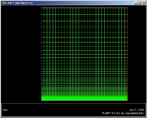
(click picture for larger image)
...
The values in the Model Constants box are constants used in the k-epsilon turbulence equations. These values for the Model Constants are well-accepted for a wide range of wall-bounded shear flows. Leave all values in the Model Constants box set to their default values.
Click OK.
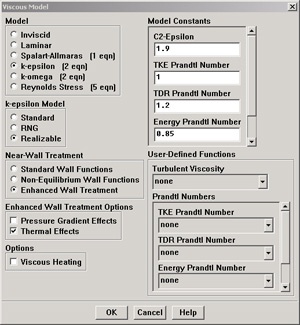
(click picture for larger image)
Define Material Properties
...
Change Density to ideal gas because we are treating the flow as compressible. FLUENT will calcualte the density of the flow at each point based on the pressure and temperature it calculates at that point. Leave Cp set as the default value of 1006.43. Change Thermal Conductivity to 9.4505 e-4. Change Viscosity to 6.667e-7. Scroll down to see Molecular Weight. Leave Molecular Weight set to the default value of 28.966. These are the values that we specified under Problem Specification.
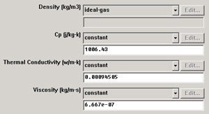
(click picture for larger image)
Click Change/Create. Simply clicking close without clicking Change/Create will cause these properties to revert back to their default values.
...
Move down the list and select inflow under Zone. Note that FLUENT indicates that the Type of this boundary is velocity-inlet. Recall that the boundary type for the inflow was set in GAMBIT. If necessary, we can change the boundary type set previously in GAMBIT in this menu by selecting a different type from the list on the right. Click {*}Set....
{}{*}
Enter 1 for Velocity Magnitude. This sets the velocity of the fluid entering at the left boundary to a uniform velocity profile of 1m/s. Set Temperature to 353K. Change Turbulence Specification Method to Intensity and Viscosity Ratio. Set Turbulence Intensity to 1 and Turbulent Viscosity Ratio to 1. Click OK.
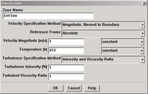
(click picture for larger image)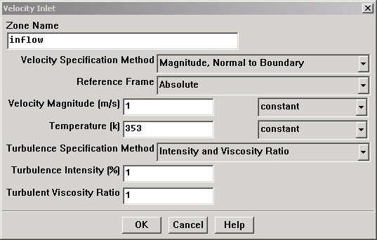
Choose outflow under Zone. The Type of this boundary is pressure-outlet. Click Set.... The default value of the Gauge Pressure is 0. The (absolute) pressure at the outflow is 1 atm. Since the operating pressure is set to 1 atm, the outflow gauge pressure = outflow absolute pressure - operating pressure = 0. Because we do not expect any backflow, we do not need to set any backflow conditions. Click Cancel to leave the defaults in place.
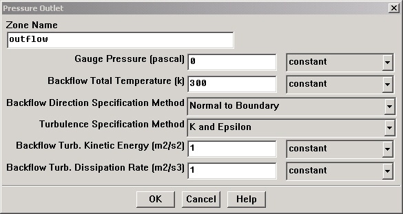
(click picture for larger image)
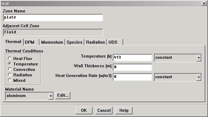
Click on plate under Zones and make sure Type is set as wall. Click Set.... Because we have a heated isothermal plate, we need to set the temperature. On the Thermal tab, select Temperature under Thermal Conditions. Change Temperatureto 413. The material selected is inconsequential because the plate has zero thickness in our model, thus the material properties of the plate do not affect the heat transfer properties of the plate. Click OK.
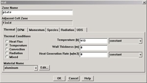
(click picture for larger image)
The last boundary condition to set is for the top of the flow field. Click on top under Zones and make sure Type is set as symmetry. Click Set... to see that there is nothing to set for this boundary. Click OK.
...