Grit Removal Innovative Technologies (GRIT) Team
Introduction
| Excerpt |
|---|
The current design of the AguaClara entrance tank was created after difficulties with grit clogging the flocculator at Agalteca and Marcala. The solution to the grit problem was to make a large entrance tank that is effectively a horizontal flow sedimentation tank, which would settle out larger "grit" particles. The entrance tank could be made smaller by making a more effective grit removal system that uses plate settlers that double as flocculator baffles. This section of entrance tank could be integrated into the first channel of the flocculator. By Because of past problems involving grit clogging flocculators, the GRIT team explored grit removal design using plate settlers before flocculation, deciding on an iteration of design called the Channel GRU. It decreases the plant’s plan view area by reducing the size of the entrance tank or integrating it into the flocculator, the plan view size of the overall plant will decrease. This means a decrease in plant construction costs, ensures even flow distribution using creative plate-to-floor geometry, and incorporates chemical dosing and rapid mix after grit removal. This design has been sent to Honduras for construction. |
Current Research
The current AguaClara plant design requires a large entrance tank to settle out grit particles prior to the flocculator. Grit removal by horizontal flow sedimentation prevents the settling of these large particles in the flocculator (a phenomenon that has been observed in several AguaClara plants to negatively affect plant flow and operation). The purpose of the Grit Removal Innovative Technologies (GRIT) team is to redesign the current grit settling system by introducing plate settlers prior to the flocculation unit. In doing so, the plan-view area needed to settle out grit will be greatly reduced, decreasing construction costs and overall AguaClara plant size. This paper outlines the GRIT team’s process exploring plate settler design options that act either as sedimentation units only, or as combined flocculation and sedimentation units.
...
Over the course of the Spring 2015 semester, the GRIT team has developed three potential grit removal designs, created visual mock-ups of each, and even sent a detailed design of the best iteration to Honduras for implementation in a small-scale plant. The first iteration, a combined grit removal and flocculator system, integrated grit removal capabilities into the flocculator baffles, but was ruled out early in our design process due to its inefficient use of space, its drastic change on the flocculation unit design, and its construction and cleaning impracticalities. The second and third iterations were both based on the idea of creating a tightly packed series of plate settlers (we call this a Grit Removal Unit, or GRU), analogous to the ones used in current sedimentation tank design, used before the flocculation process and designed to settle out grit specifically. The second iteration placed this GRU inside the entrance tank, while the third iteration placed it within the first flocculator channel. After analyzing space needed, flexibility of design, and capacity for rapid mix/ coagulant dosing integration, the third iteration was chosen as the optimal grit removal design and is well on its way to being constructed in Honduras!
Final Design: The Channel GRU
General Design
Overview
The Channel GRU is a grit removal unit, similar to the one described above, that is instead placed at the very entrance of the flocculator. bundle of evenly spaced plate settlers, similar to those in the sedimentation tank, .Using the same fundamental design parameters as the Channel GRU, the Entrance GRU is a bundled set of closely-spaced plate settlers. However, as the name implies, the GRU would be placed within the entrance tank, which in our previous designs was just vestigial unit. A sketch of our most recent design of the Channel GRU is shown in the diagrams below.
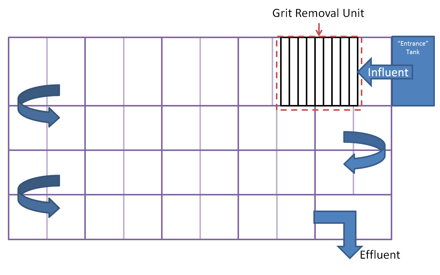
Figure 31.a. Top view of a flocculator with a GRU at the entrance of the first flocculator channel. The entrance tank, like in the GRF channel design, will only consist of vestigial elements, such as the trash rack.
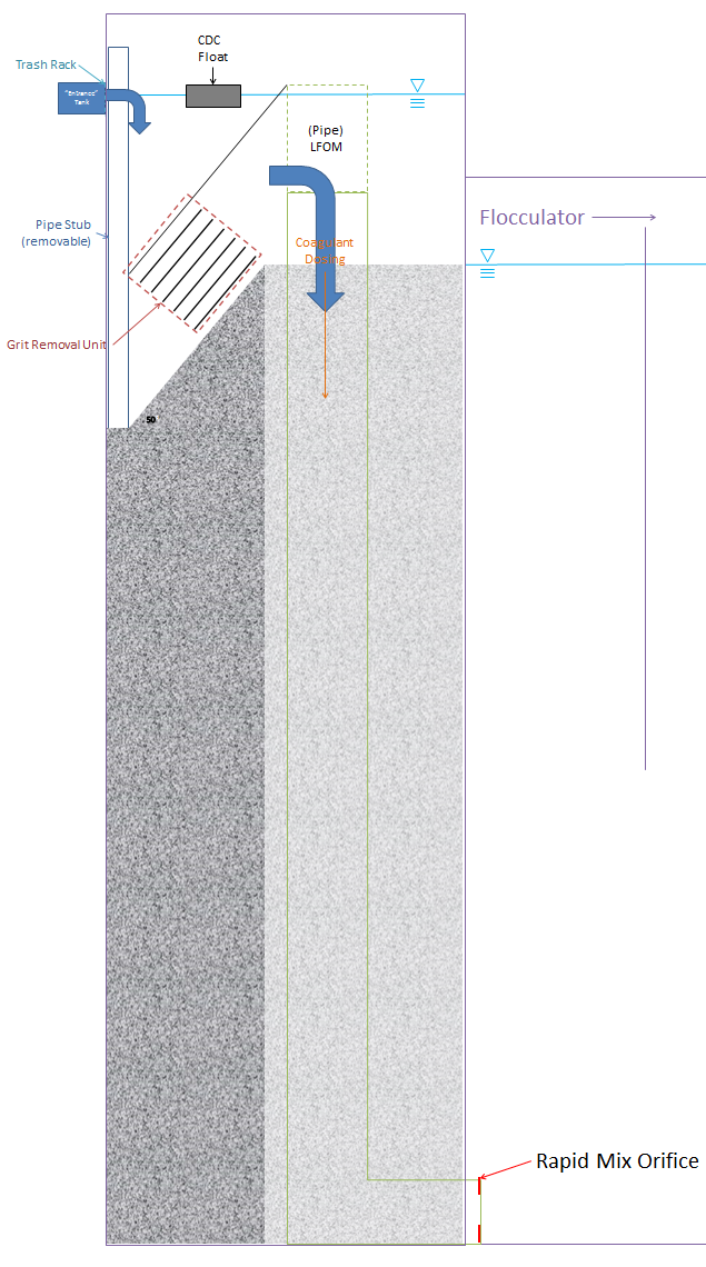
Figure 31.b.i. A big-picture side view of how the Channel GRU may look. This is a to-scale diagram of a 4L/s design, given a flocculator depth of 2m.

Figure 31.b.ii. A detailed view of the design shown in Figure 31.b.i.
Plate Angle
There have been several noticeable design changes to this Channel GRU that have diverged from typical sedimentation tank design. Firstly, the 50° angle of the inclined floor is also the angle of the plate settlers and was set as a compromise between typical design angles for the plate settlers (60°) and hoppers (45°), whose purpose the inclined floor mimics.
...
Equation 1: A list of the governing equations used in the final design based on fluids and geometry.
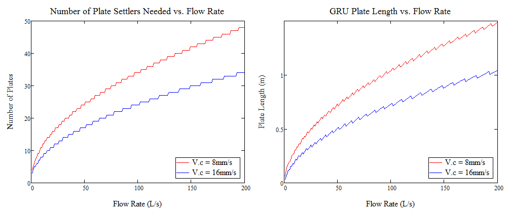
Figure 42.a.i. These two graphs describe the relationship between flow rate and the number of plates needed based on geography, and therefore length of each plate based on this number.

Figure 42.a.ii. These two graphs that relate the optimal length and height used by the GRU based on various plant flow rates.
...
Due to the small spacing between the plates (2.5 cm), there is a concern with coagulant loss to the plates’ surfaces. Additionally, dosing grit with coagulant is wasteful because grit particles are already large and heavy enough to settle out by themselves. Therefore, it is more practical to dose coagulant into the water after the GRU in this design. Rapid mix may be achieved the same way it currently is, with a rapid mix orifice at the junction of the inlet pipe and the flocculator. Then we could incorporate chemical dosing within that jet, saving coagulant and eliminating the need for a separate rapid mix unit. The LFOM, CDC float, and trash screen in this case (Figure 31.b. shows where we have placed all of these components in the design). We are considering having the sloped floor extend into an LFOM weir that sets the chemical dosing and aids in rapid mix.
...
The pipe stub that is used to plug the drain along that wall of the flocculator will not impede this flow, as the water can flow around it. The sloped floor of the GRU will be constructed such that, at the lower end, all of the grit will be funnelled towards the drain pipe, so that all grit can be removed at once. If this design is integrated into the layout of a plant as it is currently built, the drain that is covered by the pipe stop will empty into the drain channel that is already used by the flocculator and sedimentation drains. Future designs may change this configuration; if so, the issue of drainage and how to redirect the settled grit into wastestreams will have to be reconsidered.
4 L/s Design for Honduras
With about a month left of the semester, the team was asked to design a grit removal system for a potential plant to be built in San Juan Guarita. The plant would be integrating various new technologies into its 4 L/s design, along with grit removal. We decided on utilizing the last iteration of our design, the Channel GRU, for this plant design after considering all the pros and cons of each iteration. The resulting design was coded into the design code, and AutoCAD representations of the entire plant, including the Channel GRU, were drawn.
Figure 3.a.i. A zoomed-in view of the GRU, which is elevated above the rest of the flocculator channel (to the right). The red pipe is the pipe stop, the blue pipe on the left is the water inlet, and the blue pipe on the right is the LFOM.
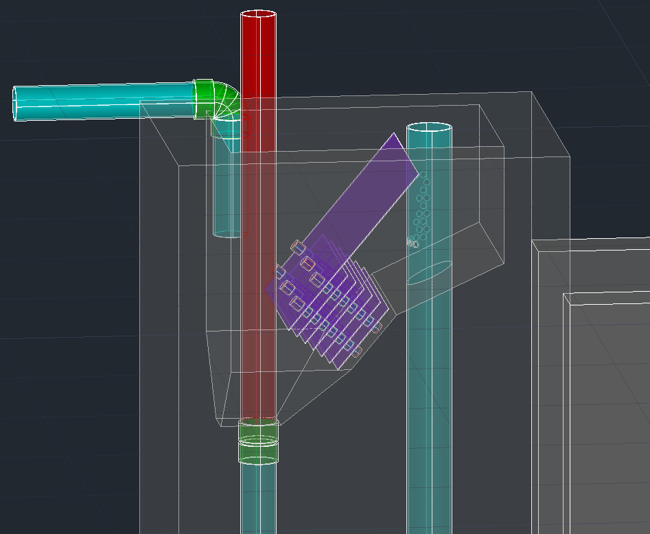
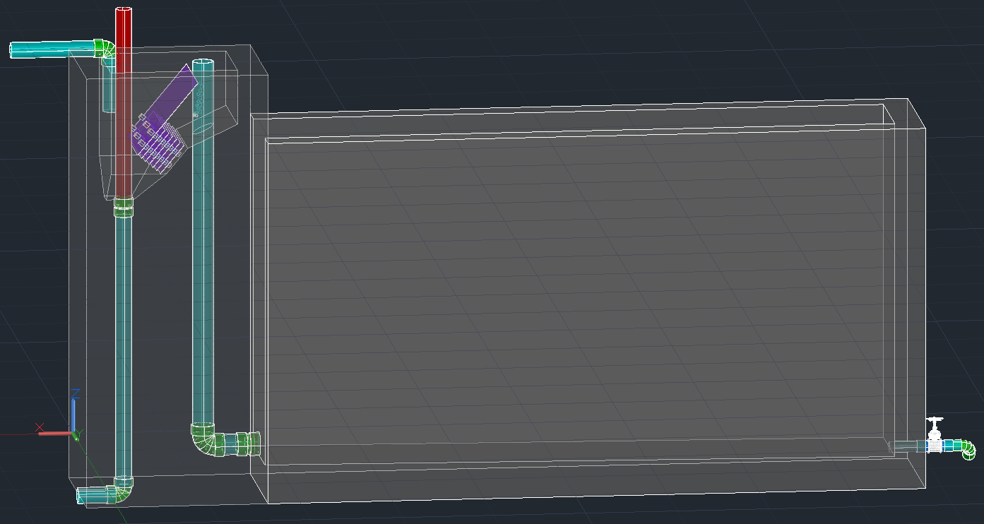
Figure 3.a.ii. The zoomed-out version of the entire flocculator channel, including the GRU, for scale. This length is the same length as the sedimentation tank (hidden).
For a 4 L/s plant and a settle capture velocity of 8 mm/s, there will be 7 plates, most of which will be 17.9 cm long (the only exception being the long topmost plate, as shown in the drawings above). The overall planview length of the unit (not including the concrete walls, drain pipe, or LFOM) is 26 cm, while the total height is 43.1 cm. These dimensions are reflected in Figure 3.a.
Future Work
While the team has decided on the best type of design for grit removal in AguaClara plants, there is still work that can be done regarding the grit removal problem. If future teams continue working on the grit removal problem, they could first keep in contact with APP and the engineers in Honduras, who are already working to implement the 4 L/s GRU designed above. As the design, construction, and future utilization occurs, feedback on the strengths and weaknesses of the design we came up with can help tweak it into a more efficient, more user-friendly design.
...
| Section | ||||||
|---|---|---|---|---|---|---|
|
| Column |
|---|