 Sign-up for free online course on ANSYS simulations!
| Include Page | ||||
|---|---|---|---|---|
|
| Include Page | ||||
|---|---|---|---|---|
|
...
Author: Benjamin Mullen, Cornell University
...
Mesh
Launch the Mesher
Now that we have completed creating the geometry of the domain, we are ready to mesh it. Return to the Project Schematic Window. In the Project Schematic window, double-click the Mesh box  to launch the mesher.
Note: If you created the geometry in SpaceClaim, you will need to perform an additional step here. Once the mesher is open, look in the tree outline and highlight Geometry > FFF\Surface, which will be your domain. Under Details, find Material > Fluid/Solid and set it to Fluid.
Mapped Face Meshing
First, we will apply a mapped face meshing (in later versions this is simply called face meshing instead), which will give us a regular mesh. First, in the Outline window, click  to show the Mesh menu in the menu bar. In the Meshing Mesh Menu, select Mesh Control > Mapped Face Meshing. In the Graphics window, click on the domain face , hold down CRTL, and select both domain faces to select it, then in the Details window, click Geometry > Apply. (Note: If you created the geometry in SpaceClaim, you will only have one domain face, which is okay. The reason we split the domain in older versions of ANSYS was because the mesher had trouble giving a high quality mesh if we didn't.)
Body Sizing
Next, we will create a body sizing for the elements that will make up the domain. In the Mesh Menu, select Mesh Control > Sizing. Next, select the body selection filter in the menu bar:

Next, select the surface in the graphics window. In the Details window, select Geometry > Apply. Now, we want to change the element size. In the Details Window, select Element Size > Default and change the value to 0.05 m.

Generate the Mesh
Now, we are ready to generate the mesh. Generate the mesh by clicking  in the menu bar or by going to Mesh > Generate Mesh. The final mesh should resemble the one in the figure below.

Named Selections
Now, we need to create named selections to use when we set boundary conditions. To create a named selection, first ensure that the edge selection filter  is selected. Next, left-click on the desired edge you wish to name (multiple edges can be selected while holding down CTRL), then right click on the edge and select Create Named Selection.
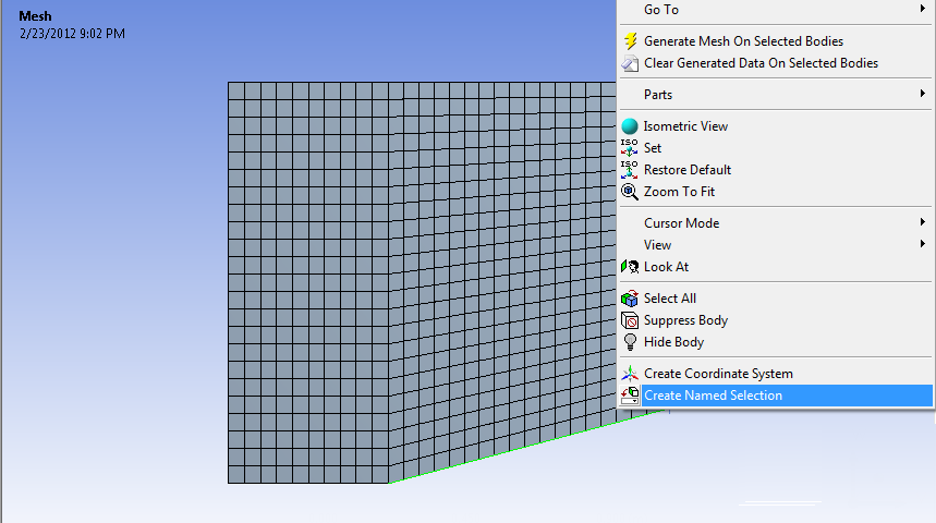
Once you select Create Named Selection, a dialogue box will appear where you will enter the desired name of the boundary. Use the diagram below to name all of the boundaries of the geometry.
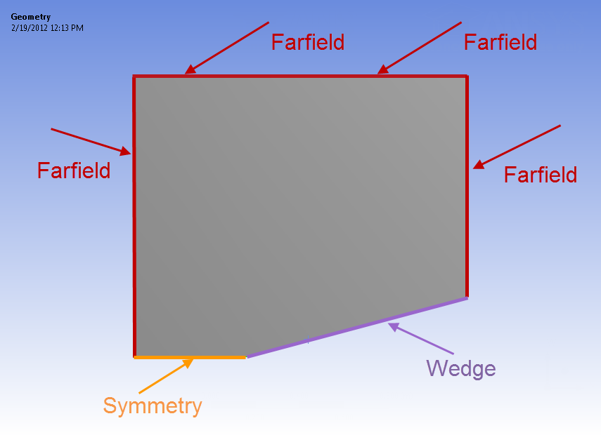
| Info |
|---|
There are 4 edges that make up the farfield, and they can all be named at once by holding down CTRL, left-clicking all of the edges while holding down CTRL, then right-clicking and selecting "Create Named Selection." |
Once the selections are all named and the mesh is created, you may save the project and close the mesher.
Go to Step 4: Physics Setup