 Sign-up for free online course on ANSYS simulations!
| Include Page | ||||
|---|---|---|---|---|
|
| Include Page | ||||
|---|---|---|---|---|
|
Mesh
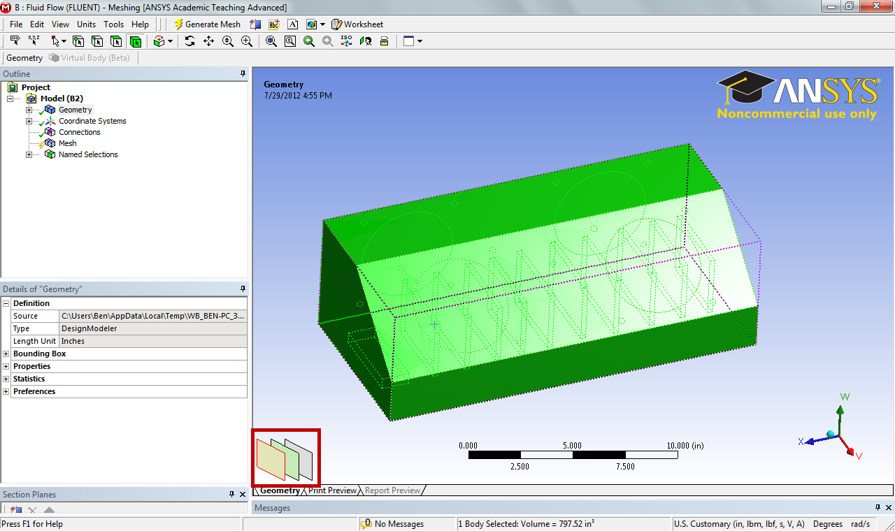
Open the Mesher and Suppress All Bodies
Open the Mesh by double clicking  in the Project Schematic window. Give some time for the geometry to load. The first thing we will want to do is suppress all of the geometry bodies except the fill geometry we created in the last step and all of the chips that will be creating heat. This will greatly simplify the solution and still give us the information pertinent to the problem statement. In the Outline window, expand Geometry, expand Part and select all of the Solids in the list that correspond to the list.
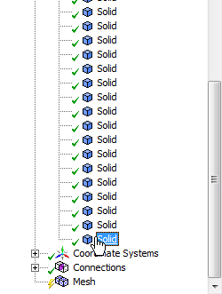
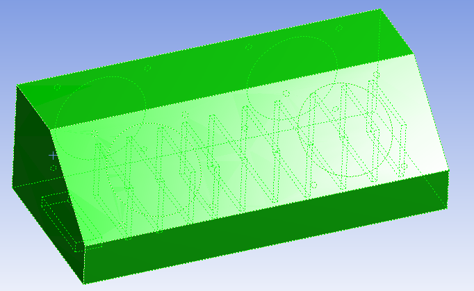
The solids select should represent the fill geometry (the empty space) inside of the box and the chips inside of the box. Verify that this is correct.
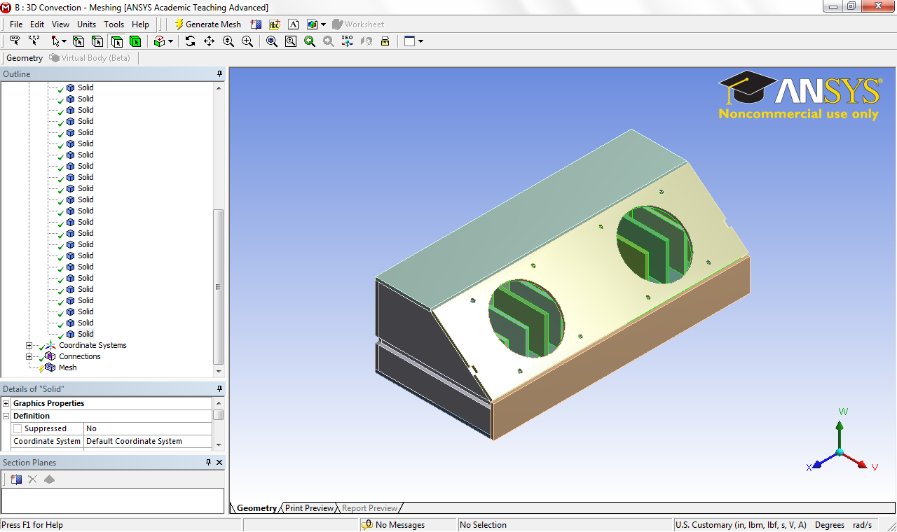
Once you are sure you have the correct geometry, right click Solid and select Suppress All Other Bodies. This should leave only the fill geometry and the chips visible.
Create Named Selections
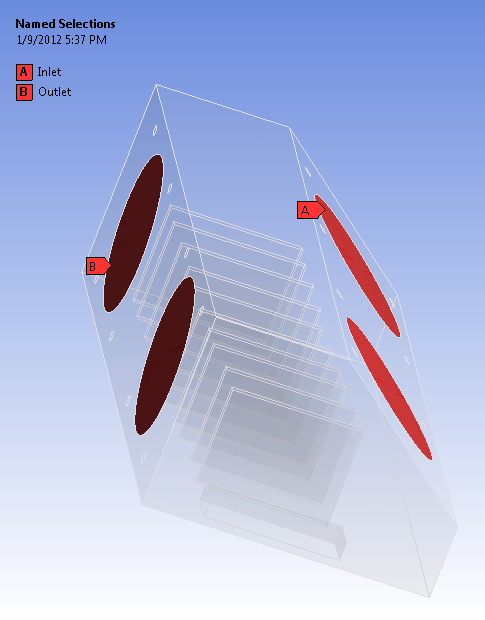
Inlet and Outlet
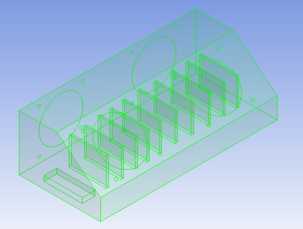
Now, we need to create the named selections that we will use to create boundary conditions. First, we will select the geometries that make up the inlet of the electronics box. Using the Face Selection Filter  , select the two faces that correspond to the inlet of the box (Use CTRL to select more than one surface).
When the two surfaces have been selected, right click and select Create Named Selection. Name the selection, Inlet. Repeat the process for the two holes corresponding to the outlet, and name the selection, Outlet.
Heat Generation
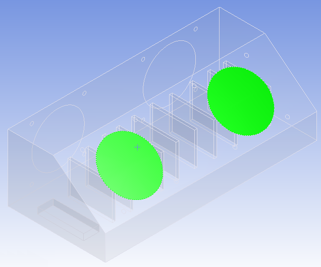
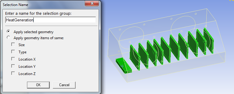
Now, we need to select chips that will generate heat. However, because the electronic boards are behind other surfaces, it is a little bit more tedious to select the surfaces. First, select the body selection filter. Once again, hold down CTRL to select multiple bodies. Next, click on an electronic board. Because the boards are behind surfaces, ANSYS will select the surface on top, as below.
In order to select the surface behind the top surface, we need to make use of the layer tool, in the bottom corner of the graphics window.
Now, while pressing CTRL, click hover over the different layer options until you have identified the surface you wish to select (in this case, a surface on the electronic board); click on that layer. Then, while still holding down CTRL, click the top layer to unselect the top surface. Repeat this process for the ten vertical chips and the battery. When you have finished selecting the surfaces, right click, and create a named selection and name it, HeatGeneration.
Generate Mesh
Due to the high number of elements needed to generate the mesh, we will be using the default mesh in order to cut down on computational time. In the Outline window, select Mesh  . In the menu bar, select Mesh > Generate Mesh. This will create the basic mesh. Close the mesher and save the project.
Go to Step 4: Physics Setup
Go to all FLUENT Learning Modules
| Panel |
|---|
Problem Specification |
...