 Sign-up for free online course on ANSYS simulations!
Step 4: Specify geometry
Overview
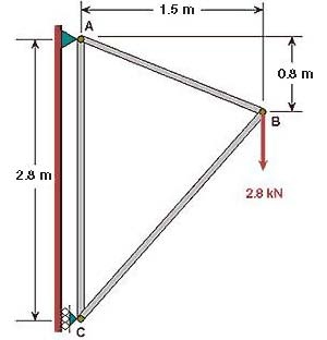
Since we are using the 2D Spar element, we can represent each truss member by a line. A line can be created by joining two keypoints (ANSYS terminology for vertices). So we'll need three keypoints, located at A, B and C in the figure below. We'll locate the origin of the coordinate system at C and number the keypoints at A, B and C as 1, 2 and 3, respectively.
Create Keypoints
Main Menu > Preprocessor > Modeling > Create > Keypoints > In Active CS
...
The keypoints will now be displayed in the Graphics window along with a triad that indicates the origin of the coordinate system (coincident with keypoint 3 in our case) and the axes.
Check Keypoints
To check if the keypoints have been created correctly:
...
You should see the keypoint disappear in the Graphics window. You can also check that the keypoint has been deleted using Utility Menu > List > Keypoints. You can then re-create the keypoint.
Save your work
Once you have successfully created the keypoints, save your work using
...
Utility Menu > File > Save as Jobname. db
Create Lines from Keypoints
Main Menu > Preprocessor > Modeling > Create > Lines > Lines >In Active Coord
...
Close the Lines and Create menus.
Check Lines
Take a look at the list of lines that have been created:
...
Close the window listing lines.
Modifying Lines (If Necessary)
If a line doesn't look right, you can delete and re-create it. To delete a line:
...
Click on the line you want to delete in the Graphics window. Click OK. This deletes the line.
Save your work
Once you have successfully created the lines, click on Toolbar > SAVE_DB to save the database.
...